The OSC-studio explained
Introduction
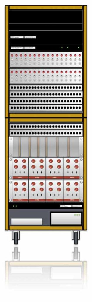
Welcome to the page of the OSC-Studio. This OSC-Studio is a modular setup of which all functions can be controlled with OpenSoundControl messages (OSC). The received OSC-messages are converted into analogue control voltages, switching relays and changing hardware connections with a voltage controlled patch-panel. In other words, you can drive a whole Voltage Controlled Studio with OSC-messages. The whole cabinet consists of 3 main parts:
VT-SPG, OSC-CV and a RC-studio.
Get started (Quick start)
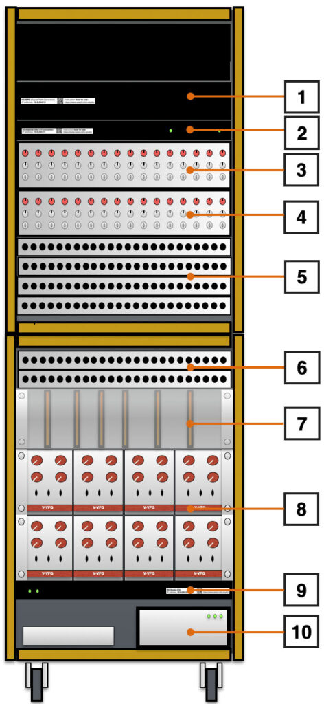
- VT-SPG. Voltage Trigger Signal Path Generator
- 32-channel OSC-CV convertor
- Shift/Gain setting for channel 1-16
- Shift/Gain setting for channel 17-32
- Banana Patch-panel with in’s and out’s of VT-SPG and the 32 CH Convertor
- Banana Patch panel with ins and outs of the RC Studio
- Misc Electronics (VSF, ADSR, Vosim, 2 x Matrix, …)
- Eight times V-FUG (function Generator)
- RC Studio OSC Receiver/Transmitter
- PowerSupply (On/Off switch) and Mac Mini
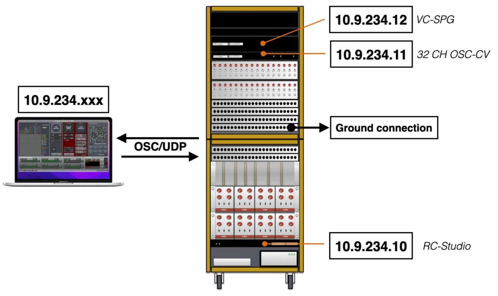
The RC-studio has an onboard ethernet switch where all 3 devices (Lantronix webservers) are connected to, so with one CAT6a cable connected to your computer you can access all devices. Be aware that you give your own computer an IP address in the same 10.9.234.xxx range.
When you start from scratch the first time, there are some settings and actions you have to take care of:
Quickstart, Step by Step:
1. Place the RC-studio in the correct position (near the equipment you want to work with). Connect the RC-studio cabinet to the mains (~240V AC) and switch it ON. This can be done by flipping the switch on the front (lower left). The 3 led’s on the power-supply (lower right) should light up.
2. Connect your computer directly to the installed CAT6 cable and make sure your IP address is in the 10.9.234.xxx range. For example give your computer IP-address 10.9.234.100. You have to avoid the numbers xxx.10,11 and 12. These are already taken by the RC-studio. In case you work with a Macintosh, it’s preferable to create a separate netwerk location within the network settings.
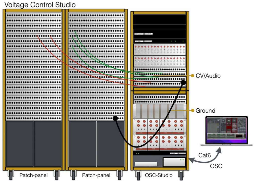
3. If you want to work with the VCS studio setup, you have to make sure the GROUND is connected (see picture below).
4. Depending on what module you want to use, install the proper Max patch and start sending OSC. Have Fun! 😉
5. If you run into challenges (the RC-studio does not do what you expect it to do:), … please contact me: info@ipson.nl
VT-SPG (CompLex)
VT-SPG is short for Voltage Trigger Signal Path Generator – the device is also known as the CompLex. This generator, or matrix has 16 audio inputs and 16 audio outputs and can be driven with signal triggers, control voltages or by OSC. This project is already explained in detail here. This version of the VT-SPG is created with banana plugs and thus easy to interface with the Sonology Voltage Control Studio 6.67 and the Composition Electronics Music Studio 6.78.
The VT-SPG (CompLex) in this studio has IP number 10.9.234.12OSC-Messages
To generate the right OSC-messages a Max/Msp patch can be used. See the figure below. The only thing this patch does is generating OSC-messages to drive the VT-SPG. If you want to use other software (SuperCollider or Puredata for example), please feel free to do so.
Patch osc-message (/pa):  /pa [byte 0] [byte 1] … [byte 8]
Store osc-message (/st):  /st [byte 0] [byte 1] … [byte 8]
Config osc-message (/cf): /cf [byte0]
The detailed OSC syntax explanation for the VT-SPG can be found here. If you want to work with the VT-SPG without programming the right OSC-messages, please checkout the the Max-patch below. You can download the Max file (sorry for the chaotic setup) or the application, if you do not have Max/Msp installed.
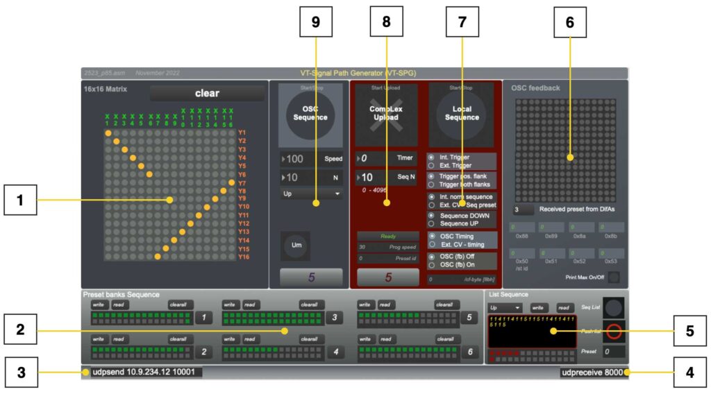
- The matrix. Clicking on the gray dots wil instantly send a /pa string to the CompLex, activating this connection. If a preset is created, this preset can be stored by shift-clicking on one of the locations in [2].
- Preset banks. In this box the presets created in the matrix [1] can be stored. The preset can also be written to file or read from file. To create a physical connection, click on the right junctions in the matrix[1]. If the dots are lighting up in yellow, the connections are active and the preset can be stored. Storing a preset can be done by clicking on the right number preset box in [2] and hold down the shift key at the same time. When all presets are made and it is time to sequence through the different presets, select the right number (1-6) in box [2] and start the sequence with the start button in box [8].
- Udpsend. The computer has to send the OSC-messages to the right ip-address and port. On the left side in box[3] the ip-address and port of the CompLex has to be filled in. In the RC-studio the IP address is 10.9.234.12 The port number should be 10001.
- Udpreceive. On the right side the receiving port is defined. Port 8000 will be set to receive OSC-messages from the CompLex, unless it is configured differently in the embedded webserver (see getting started).
- Sequence from lists. When you created presets, but you want to sequence through the presets in a specific order other than up/down, you should create and use lists. If the button ‘Seq List’ is active (green, or blue) the OSC sequence start/stop [9] will sequence from the list [5]. In this list presets-id’s are written from the selected bank at [2]. Before the list can be sequenced, the list should be ‘pushed’ or activated (red/black button).
- OSC visual feedback. This part of the patch shows the incoming OSC-messages from the CompLex in order to have (visual) feedback. Whether the CompLex will send OSC messages back to the computer depends on the settings of the switches or the settings of the controls explained at [6]. When the ‘print Max’ switch is turned on, the patch will print the vales that are send to the CompLex in the max-window. This option is for controlling or testing purposes only – it will slow down the total performance of the Max patch considerably.
- Configure CompLex. This part of the patch controls the configuration. The switches in this box replacing the physical switches on the different models. The biggest button on top start/stops the local sequence. The following options can be chosen going down in the patch: Internal or external trigger; Only positive or both positive and negative flank reaction for external trigger; Internal normal sequence (up/down) or ext. cv-sequence; At normal sequence up or down; The source for the speed (timing) from OSC (the patch) or from ext. Cv-speed; The last one is switching On/Off the OSC-feedback.
- Uploading presets to the CompLex This box sends the /st OSC-message in order to store the presets in local memory. When the big cross (upload to CompLex) is clicked, the active preset bank, selected at [2], will be uploaded. The rest of the variables shown in this box [7] generate a new /cf OSC-message changing the timer and the amount of presets (N) of the sequence.
- OSC-sequence. This part starts or stops the OSC-sequence. If it is active the patch sends /pa OSC-messages at variable speeds and it sequences through the selected preset-bank [2]. The speed and the amount of presets of the sequence (N) can be set as well. To offer more variation a choice of Up/Down, Pendulum (up and down) or ‘Urn’ are offered. This last option ‘Urn’ sequences through a set of presets (bank) in random order, but will use all the presets at least one time before starting with the next round.
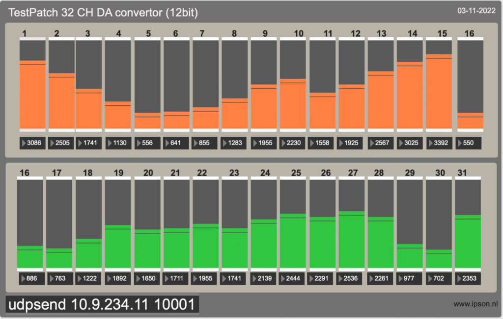
32 Channel OSC-CV convertor
The 32 channel OSC-CV convertor converts incoming OSC-messages into control voltages from (after adjustment) -5 to +5V.
The OSC-CV convertor has IP address: 10.9.234.11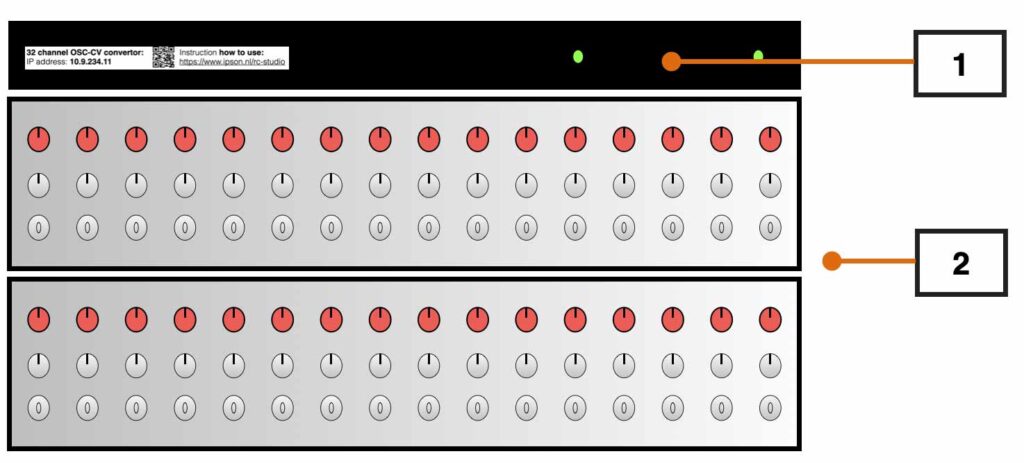
The figure above shows the frontpanel of the 32 channel OSC-CV convertor. [1] indicates the frontpanel of the 19″ cabinet that holds the OSC receiving and DA conversion electronics. When the right OSC messages are received, the led’s on the front will light up.
[2] in the picture shows 2 knobs and one switch per channel. With the switch you can determine whether you work with the original Control Voltage (CV) which varies from 0V-5V (12 bit resolution) or with a gained/offset.
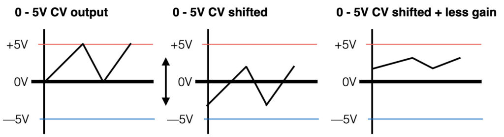
When the switch is not in the position “direct”, the internal amplifiers and gain control will be active. What does this mean? With the two controls (Shift and Amp) you can move the CV values ‘up or down’ within the range of +5V and -5V.
When the gain is set to max, the range of the CV will be 5V. When it is set to half, the range will be 2,5V. See the picture below for some more clarity.
OSC-Messages
The Max patch below shows a way to generate the right OSC-messages for the convertor. Th OSC-message for the convertor consists of 8 (32 bit) bytes with the address-tag /1 or /2, depending on the channel.
OSC-messages:
Write channel 1-16 (/1):  /1 [byte 0] … [byte 7]
Write channel 17-32 (/2): /2 [byte 0] … [byte 7]
Below the Max/Msp patch. Als this patch only generates OSC-messages with the format mentioned above. You can download the patch here.
RC-Studio
The original setup of the RC-studio was to setup a platform for testing the OSC-devices that we developed in the Electronics Workshop. Converting OSC to control voltage or relay switching, this could all be tested in the RC studio. Years ago the eight old VFUG’s (Voltage controlled Function Generators) that used to be part of the analogue studio of Sonology (Bea-5), were replaced by twelve new VFUG’s. Re-using the 8 old VFUG’s was the first step towards the RC studio as it is now.
The RC-studio has IP number 10.9.234.10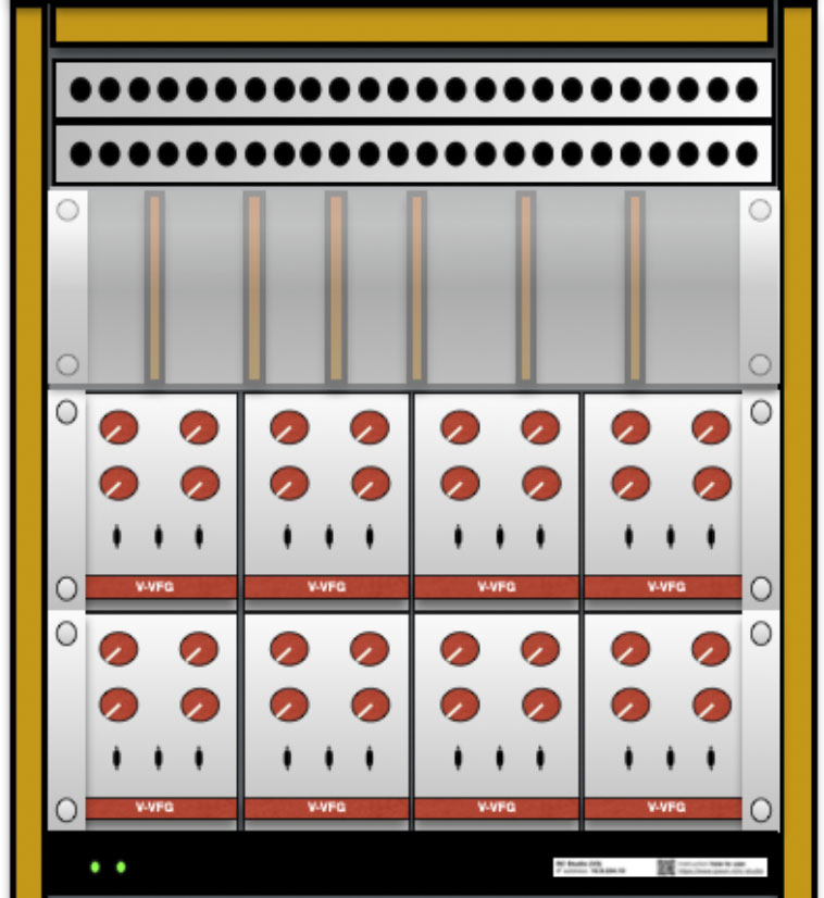
The 19” module with the plastic glass-plate in front holds all the important modules that make the RC studio what it is. The modules are build by hand on ‘Eurocard’ printed circuit boards (PCB’s) that comply with the Voltage Control Studio (VCS, 6.78) standard.
The RC-studio consists of the following modules:
1. One matrix with 16 in’s and 16 outs (/pa)
2. 8 x V-FUG’s completely drive by OSC (/rx)
3. One Voltage controlled matrix (16 in, 16 out and CV and trigger input) (/ma)
4. One 16 channel 12 bit OSC-CV convertor (/v1)
5. ADSR envelope generator (/ev)
6. Vosim
7. Noise generator
8. Variable State Filter
9. PWM Generator
OSC-messages
The Max/Msp patch shown in figure below can drive the RC-studio. It generates all the correct OSC-messages for driving the modules and the two matrices.
Write patch (/pa):  /pa [byte 0] [byte 1] … [byte 8]
Write relais VFUG (/rx): /rx [byte 0]
Write patch (/ma):  /ma [byte 0] [byte 1] … [byte 8]
Write Control voltage (/v1): /v1 [byte 0] [byte 1] … [byte 7]
Write envelope (/ev): /ev [byte 0]
This patch is a personal (partially chaotic:) interpretation, and please feel free to re-design the patch or rip it apart. Download the file here.
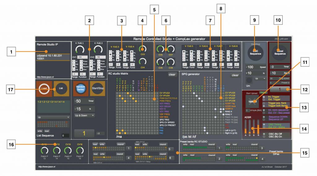
1. This is the IP number (10.9.234.10) of the RC-studio with the right port information. The Max/Msp patch sends (udpsend) all OSC data to this IP-address and port (10001).
2. VFUG 1 and VFUG 2 with the settings of wave shape, frequency range (10,100,1k,10k) and the pitch. Both VFUG1 and 2 are directly connected to CV1 and CV2 (outputs 1 and 2 of the OSC-CV DA convertor) and can not be patches to external control voltages – in other words, the pitches are fixed to CV1 and CV2.
3. The pitch control voltage can be patched of VFUG3 and VFUG4.
4. Control voltages 3 and 4 are available on input 5 and 6 of the /ma matrix.
5. The matrix object driving OSC-matrix /ma. By clicking on one of the dots of this matrix (making a connection from the input to the output) a OSC-message will be sent from your computer (the Max/Msp patch) to the RC studio. In total there are 256 connections (16 x 16) that all can be set and cleared. Storing a patch can be realized (see 15) with the use of the preset-objects. A <shift> click will store the patch.
6. More Control voltages that are available on the /pa matrix, or CompLex.
7. VFUG 5,6,7 and 8. All four pitches of these generators can be patched through the matrix.
8. This is the same object as use in (5), but it generates a different OSC-message (/pa). Also these patches can be stored in the preset object underneath.
9. Since the CompLex is a generator, there are a few different ways to sequence through presets. When button (9) is pressed, the Max patch will sequence through the active preset-bank that is indicated at (12). This is a so called local sequence. You can change the amount of presets in the sequence (1-32) and the direction (up, down, pendulum). The time in msec (milli seconds) indicates the speed of the sequence.
10. The preset-banks (1-32) can also be uploaded into the local memory of the CompLex. In this way, the sequence through the different presets can be triggered by external voltages. The configuration of the external triggers and control voltages can be set at (13).
11. Pressing this button will upload the active preset into the local memory of the CompLex generator or matrix.
12. This is the indication of the active preset bank.
13. As explained in (10), the configuration of the external voltages and triggers can be set in this area.
14. The ADSR module has 4 faders (variables) that can be changed: Attack, Decay, Sustain and Release. All four variables are being sent into one separate OSC-message.
15. For both the OSC-matrix (/ma) and the CompLex (/pa) the patches can be stored in these preset-banks.
16. Extra control-voltages that are available on the external patch panels (output).
17. Instead of sequencing in order (up/down/pendulum) through the patches in a preset-bank, you can also create a list of different preset numbers. When the button ‘List’ is active, the sequence will play according to this list.
Block schematic
The setup of the RC-studio changed many times the last years and it will keep on changing when more users share their ideas. In the figure below a complete overview is shown of all the internal and external connections. The colors that are used, refer to the colors used within the Max/Msp patch.
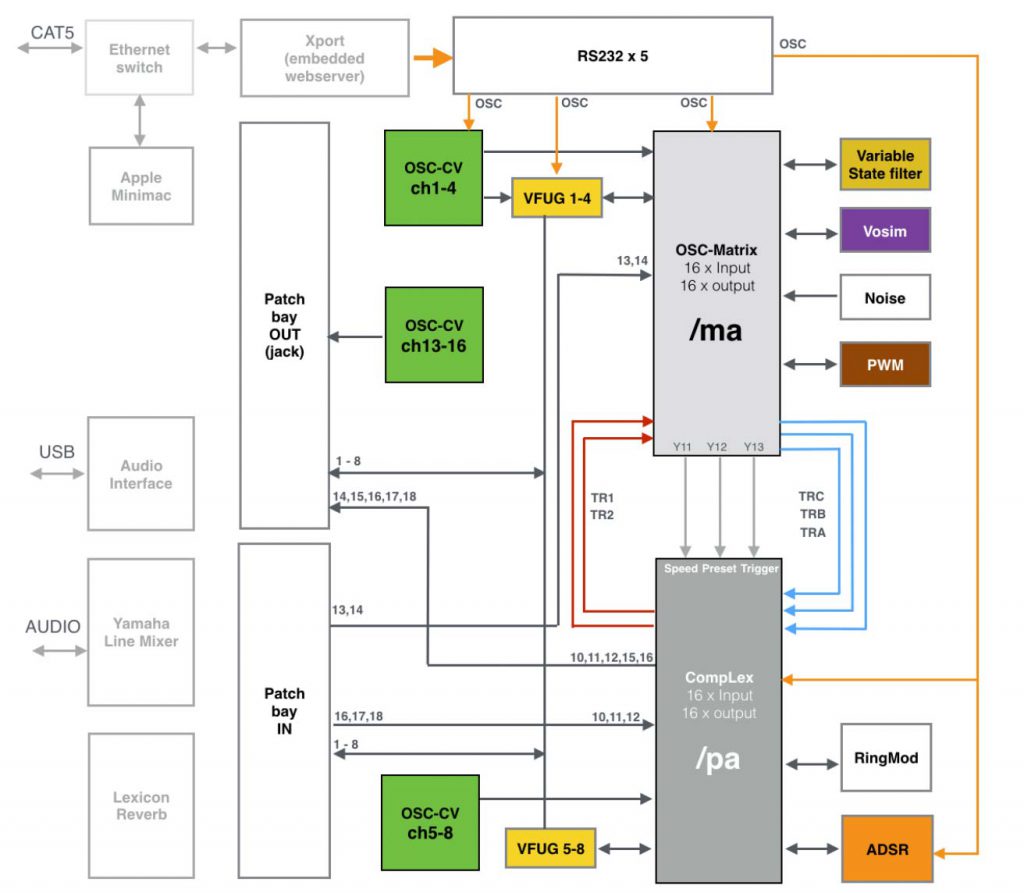
The heart of the RC-studio consists of two matrices (the two grey boxes). The first matrix (OSC-matrix, /ma, light grey) is the older matrix module (the first version I made). It is capable of switching 256 switches On/Off at once to create connections or patches.
The second one (CompLex, /pa, darker grey) is the matrix with the nickname ‘CompLex’ and is a result to my master research project. The CompLex is a voltage controlled and voltage triggered audio matrix, capable of switching at high speeds. The ‘/ma’ and ‘/pa’ indication refer to the OSC-string address-tag that has to be used to drive the matrices.
The ‘/ma matrix’ has 16 audio/cv inputs and 16 audio/cv outputs. It has multiple modules connected to it (see figure) like the Vosim, a VSF, Noise, 4xVFUG and a VC-PWM generator. It has 3 dedicated output connections that are directly linked to 3 inputs of the second matrix, the CompLex – these are TRA, TRB and TRC (transfer). The CompLex has 2 direct output connections as well, connected to the input of the OSC-matrix called TR1 and TR2.
The OSC-matrix also has 3 outputs that are directly linked to the 3 voltage control inputs: CV-speed, CV-preset and trigger input. The CompLex, also called the Voltage Controlled Signal Path Generator (VC-SPG) is capable of switching between patch presets at high speeds (audio rates). The OSC-matrix can therefor drive the CompLex matrix. Both the matrices have direct connections with the patch panels making it possible to connect to external devices – your music world!