The B&K Vocoder is a project that combines two B&K filters and multiple OSC-driven Matrices. Step 1: What is a Vocoder? If you do not know the answer to this question, but you really want to know, please check this link.
If you want to use the Vocoder in the new VCS studio (6.76),
please check this page: B&K Vocoder User manual
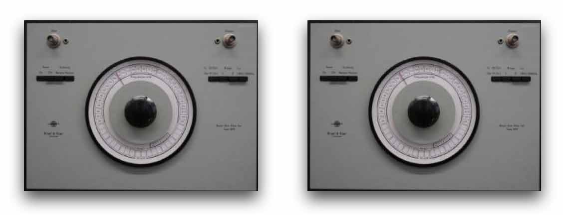
To create this Vocoder will be a big project that consists of two original B&K Band Pass Filter Sets Types 1615 (see photo) in combination with a 32×32 OSC controlled audio matrix – the CompLex. The 3rd octave B&K-filters are made in the 1970’s and make use of real big coils. This makes the sound of these bandpass filters very unique. Since we have a few of these filters and we can use the OSC-controlled audio matrix to change the routing, the whole device will be an interesting composing tool for the department of Sonology. See also the block schematic below.
Two identical Bruel & Kjear Bandpass filter 1615:
First block schematic of the B&K Vocoder:
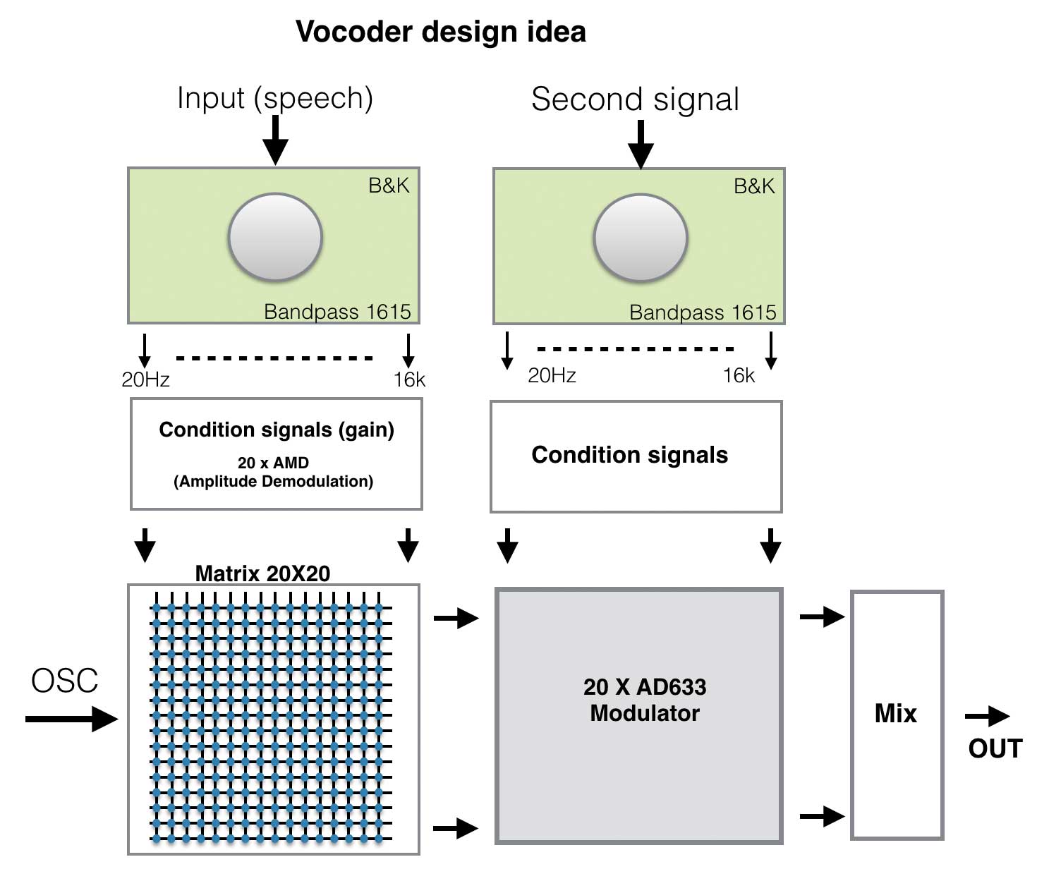 Short description of this block schematic::
The speech input signal will be split into 20 different frequency parts – the actual spectral characteristic. These separate split frequency parts will be converted to an envelope by a so called Amplitude Demodulator (or amplitude follower). These 20 x AMD’s will ‘follow or rectify’ the amplitude of the audio signal and create a low frequent control signal, that is a representative of the actual amplitude. The 20 different ‘envelopes’ will be connected to an audio-matrix (the extended CompLex ;-).
On the second input a miscellaneous signal (music, or whatever is available) can be connected. This second signal is equally split into 20 single frequency’s – exactly like the speech input. All separate split frequency parts of the second signal are now linked to 20 x AD633 ‘multiplier chips’. If the audio matrix is set to In1 = Out1, In2 = Out2, …, In20 = Out20, the 20 different amplitudes of the ‘speech’ input signal are now multiplied (modulated) with the same split frequencies of the second input.
The interesting part of this design is that we can change the audio-matrix on the fly with OpenSoundControl (OSC) or with other analogue signals and so changing the route of the control voltages. For example the envelope of the 1kHz band of the speech can now be connected to the 20Hz band of the second input. This will really create very interesting (musical) results.
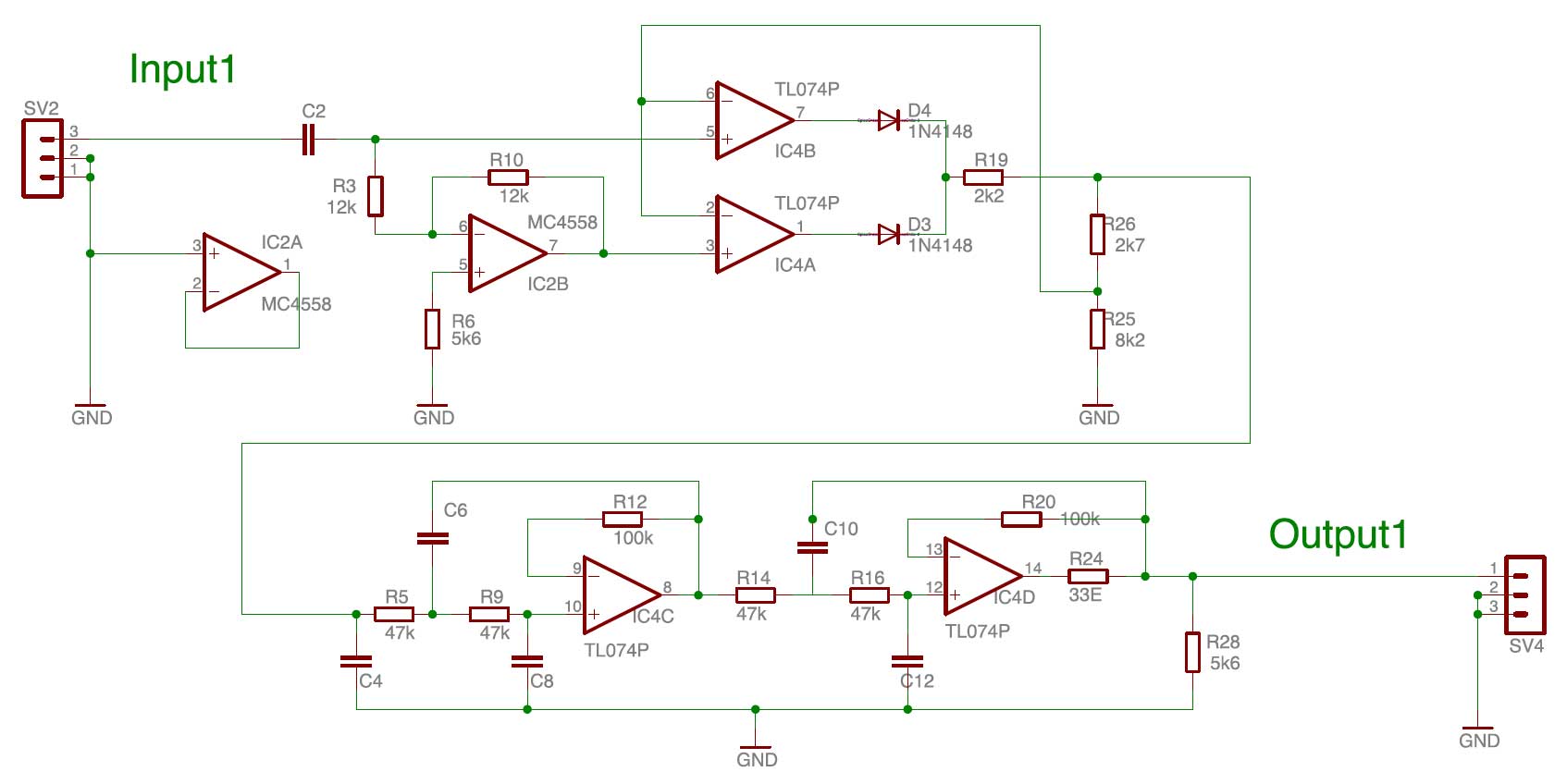
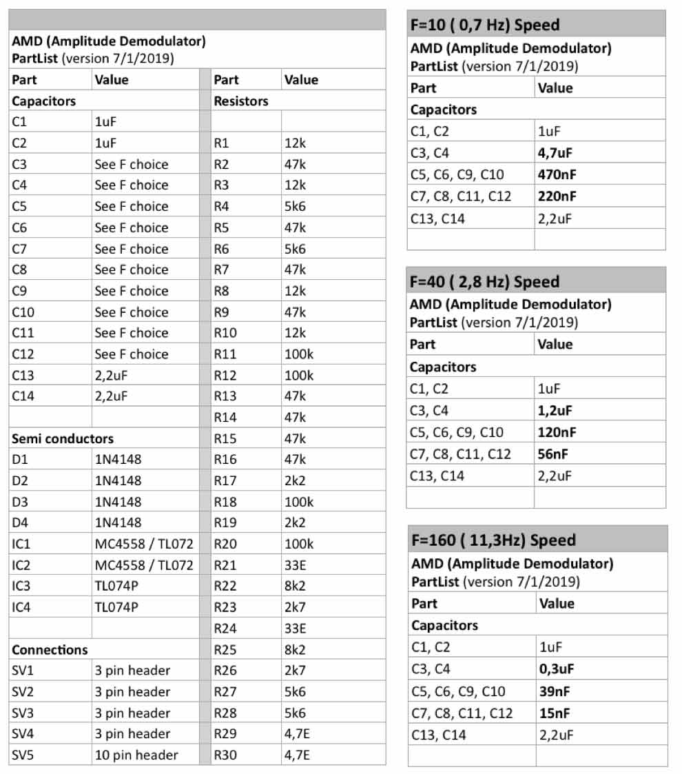
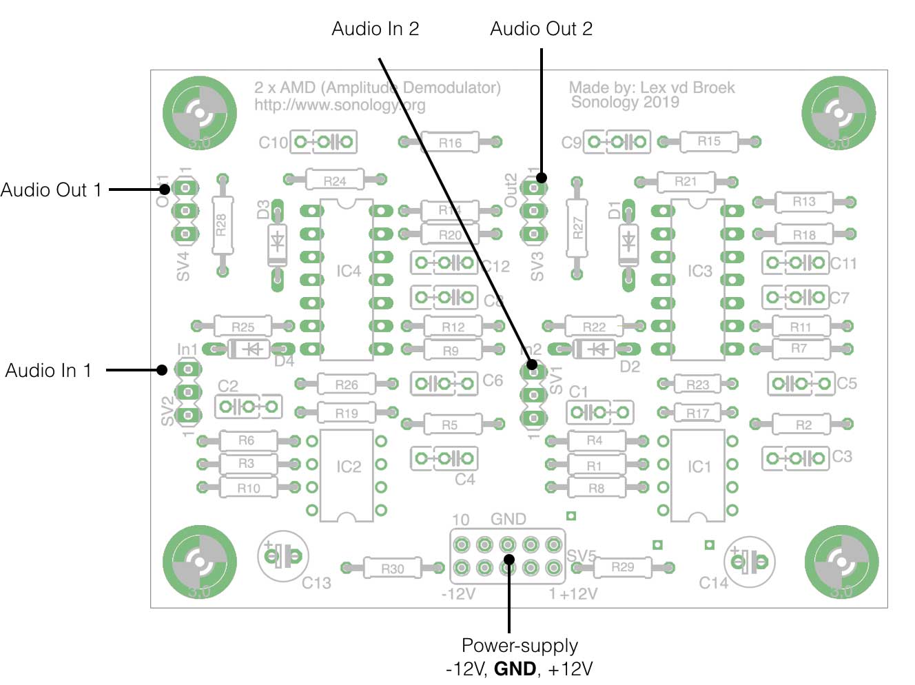
Double AMD (Amplitude Demodulators or Envelope followers)
The AMD used in the B&K Vocoder is developed at Sonology in the 1970’s. It is an amplitude follower that uses double sided rectification and also the ‘speed’ of the follower can be adjusted by setting different capacitor values. So for lower frequencies the follower can be set ‘slow ‘(F=10 / 0,7Hz). For mid- and higher frequencies the speed can be set to F=40(2,8Hz) of F=160(11,3Hz).The PCB of the AMD consists of two identical amplitude followers. In the circuit below only one channel is shown.
From input1 the audio-signal (through C2) is inverted with IC2B. IC2A is not in use in this board and is connected to ground. Both the inverted- and original signal are connected to the opamp-pair IC4A en IC4B where the diodes as part of the feed-back loop realise a double sided rectification. IC4C and IC4D are two active low pass filters placed in series (creating a steeper slope). The values of the capacitors determine the cut-off frequency and thus the ‘speed’ variable F (see table).
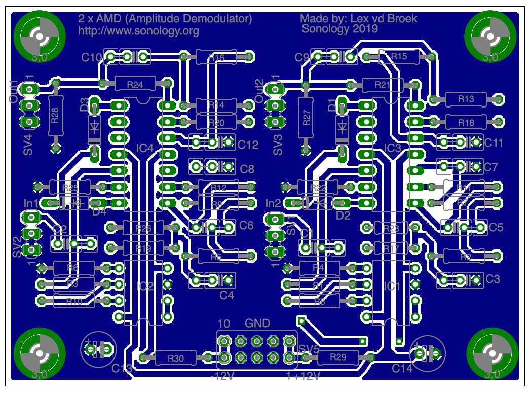
Bottom layer (soldering side)
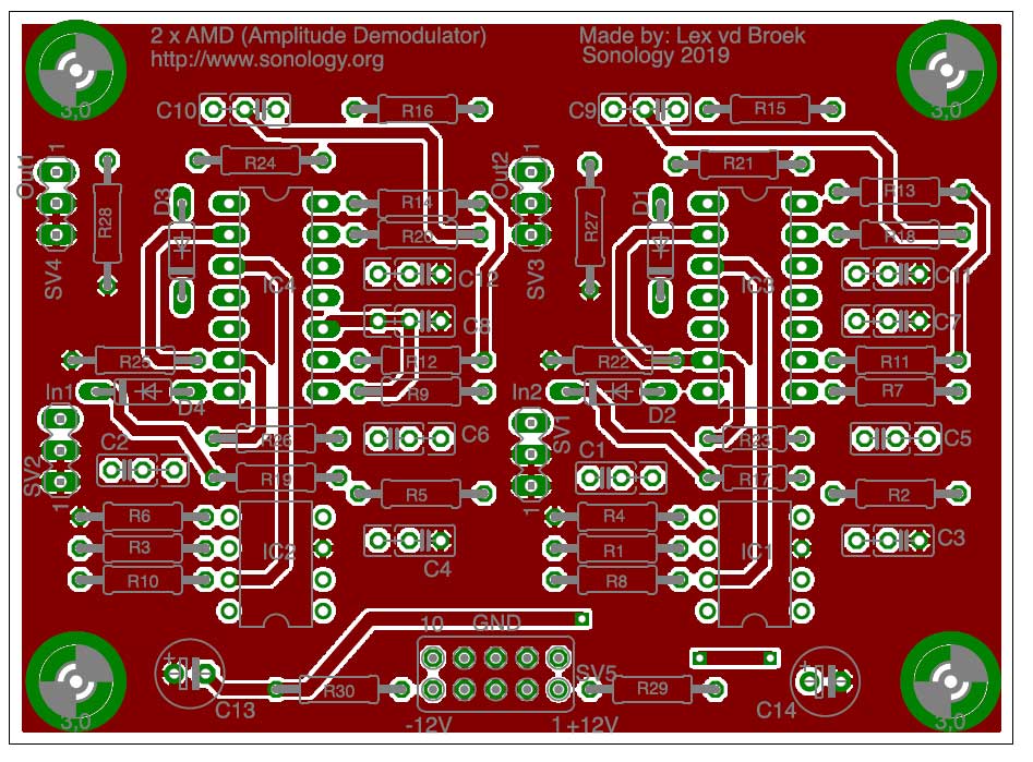
 Top layer (component side)
Pre-amp and VCA Design:
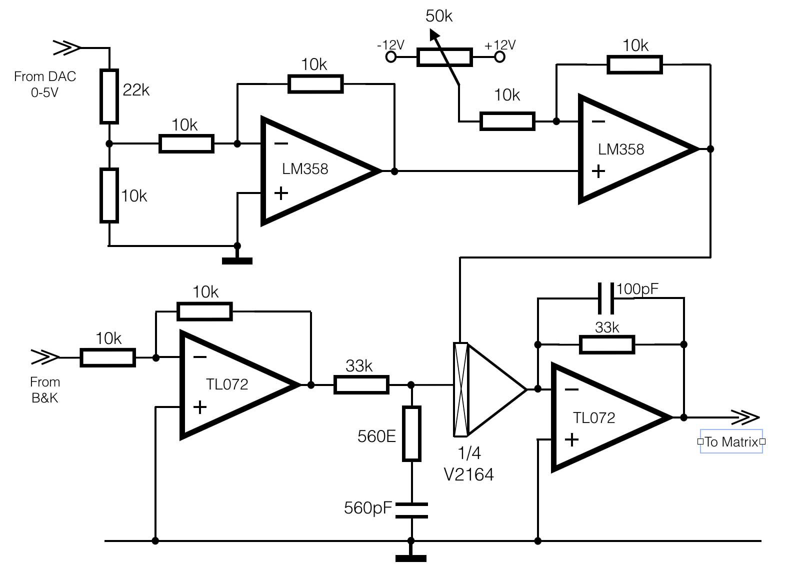 This circuit is the part of conditioning the signals and has to be build many times. First of all, the upper two opamps (LM358) convert the 0-5V values from the DAC board into -1V / +1V . This range is needed to control the VCA V2164 and have the full amplification range (around 40dB). It seems a complex solution for a simple conversion, but this design can still be adjusted in its behaviour when it is realised.
From the DAC the 0-5V is divided into 0V to +2V and inverted in the first opamp on the left to 0V- (-2V).
With the second opamp on the right the offset and amplification can be set. The output is directly connected to the CTL input of the V2164.
The lower two opamps (TL072) condition and amplify the signals coming from the B&K filters. The V2164 is a Voltage Controled Amplifier (VCA) and has a maximum amplification in this setup of around +38dB. The amplification can be set with OSC (OpenSoundControl) or through a locally mounted potentiometer on the front.
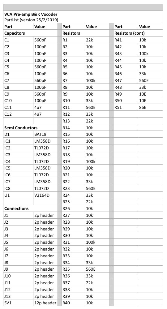
Component list:
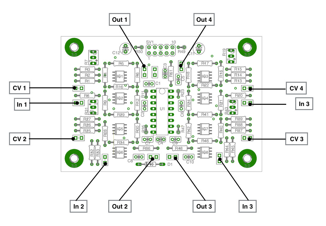
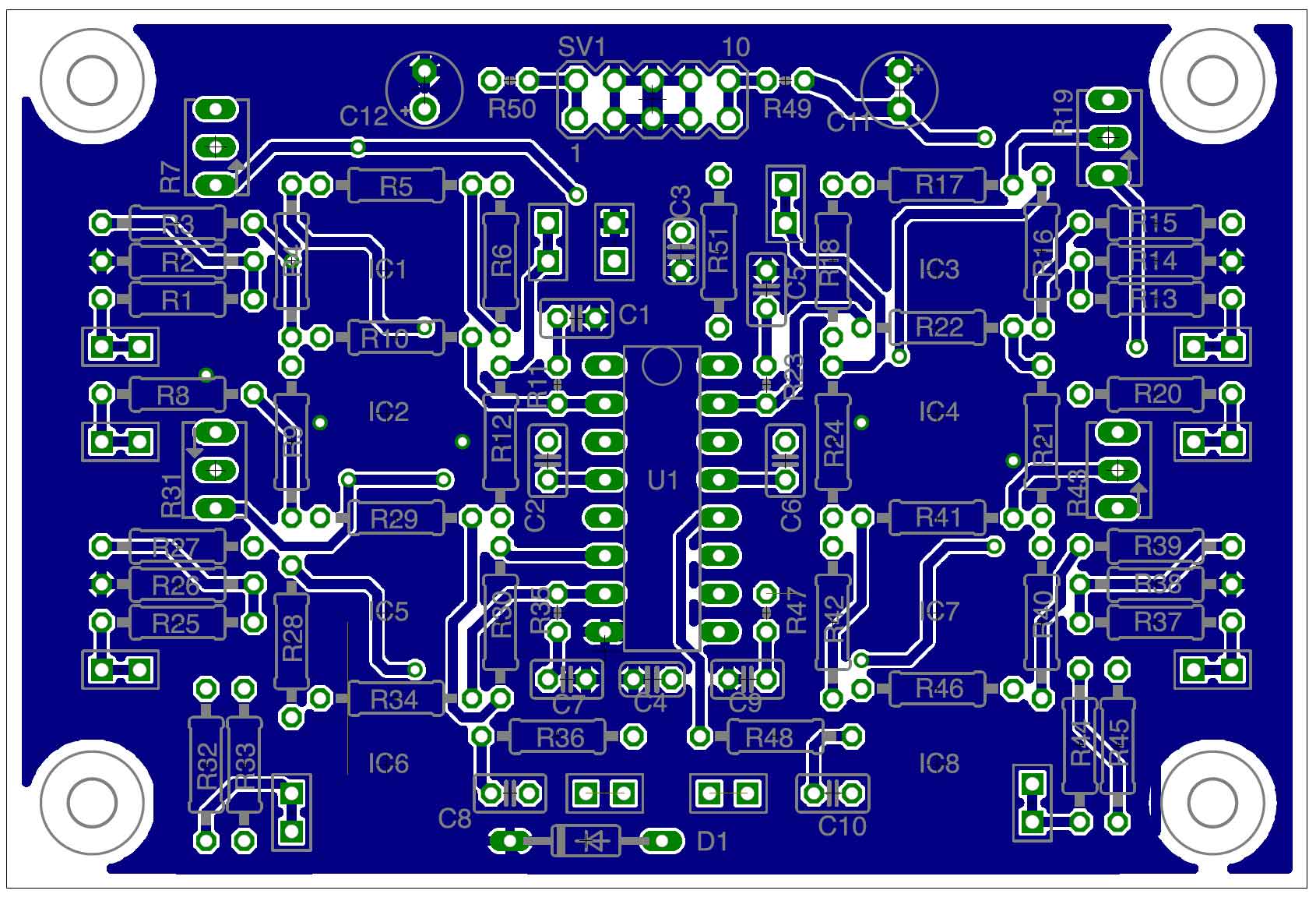
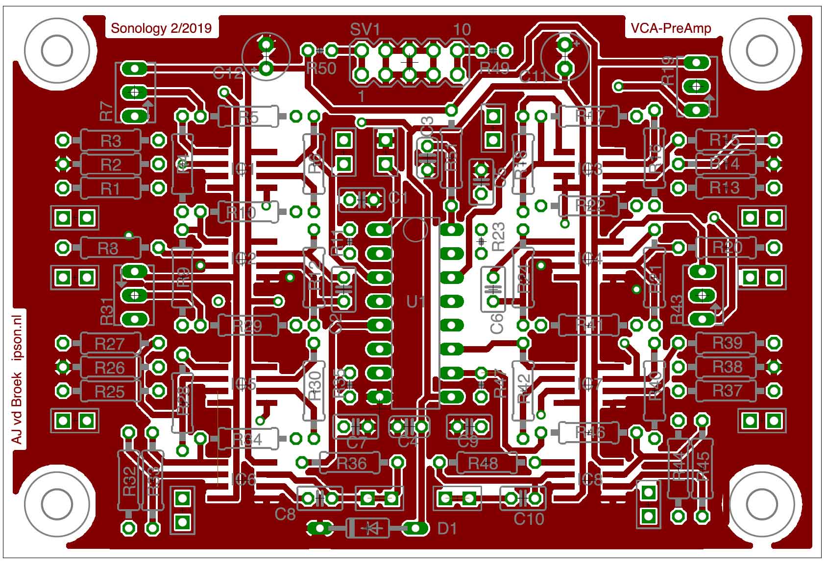
This is the Printed circuit board layout with the location of the connections. It is a quad-VCA board – so 4 times the circuit as drawn above. In the middle the VCA chip itself, the V2164D. This is a clone of the Analog Devices SSM2164 chip – which is out of production.
Bottom view pcb:
Top view pcb:
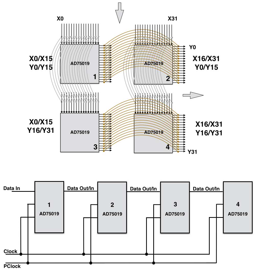
The Quad Matrix setup
To be able to create a matrix that has 32 inputs and 32 outputs, we need to combine four 16×16 chips. like shown below. Matrix number 1 represents input X0-X15 and output Y0 – Y15. Both inputs and outputs are also linked to matrix 2 and matrix 3. Matrix 2 represents X16-X32 and output Y0 -Y15.
So with 4 x AD75019 we can create a matrix of 32 x 32.