Introduction
In my experience, nobody ever reads a manual (;-), but if you want to get a better understanding about the whole configuration, communication and the initial setup of the CompLex you better read through this manual. You can also directly jump to the Quick Reference guide if you are in a hurry, but do check the OSC communication setup – it explains how you can send and receive OSC-messages in the right format.
Since you probably are a frequent user of analogue studio’s, modular synths or other techniques that require patching of cables from module to module, you will discover this Digital interface for Analogue signals to be a new interesting tool for you. Changing patch cables of your setup during a performance or recording is something you normally will not even think of, but if you are able to change patch-cables on ‘the fly’ and in-sync with external signals, it will be a new feature of your setup.
The CompLex introduces the possibility to change a set of patched cables through a matrix of 16 inputs and 16 outputs. You can store up to 32 different pre-sets (equal to 32 times 256 connections) into its local memory. If the pre-sets are uploaded and stored, you can sequence through these pre-sets by means of external control voltage (CV) or triggers to change the speed of the sequence and/or to change the choice of the next pre-set in line.
Have fun switching!
Content
What’s new
General operation
Connect interface for the first time
Run first test
OSC communication
CompLex communication
patch (pa)
store (st)
configuration (cf)
What’s new?
The CompLex is being developed as a Sonology Steim research master-project and will be regular updated. This practically means that after finishing and publishing this manual, new firmware and hardware modifications will continue to take place. In this ’What’s new?’ part of the manual the latest changes will be described. The order of the changes will be that the most recent change will be on top. During my research I maintained a log about the development and changes that took place with the different versions, but it would be out of the scope of this manual to also publish it here. In June of the year 2017, I published a complete thesis about the design of this interface as a part of my research. For now the ‘What’s new’ chapter will start in December 2016
5-01-2017 (version 86)
I managed to solve a small error within the firmware. When the CompLex was configured to convert an incoming control-voltage (cv) to the next preset-id, the sequence seemed to be unstable and run away. A small typing error within the assembly code was the problem. Solved!
19-12-2016 (version 85)
At this point the CompLex is running on firmware version v85 and the Max/Msp software patch is also named v85. All known bugs are fixed. In the previous versions (< v85) the firmware could crash if it was set to be used with external triggers. But if no external triggers were connected, the interface continued waiting and was not available anymore until a hard reset was applied.
General interface operation
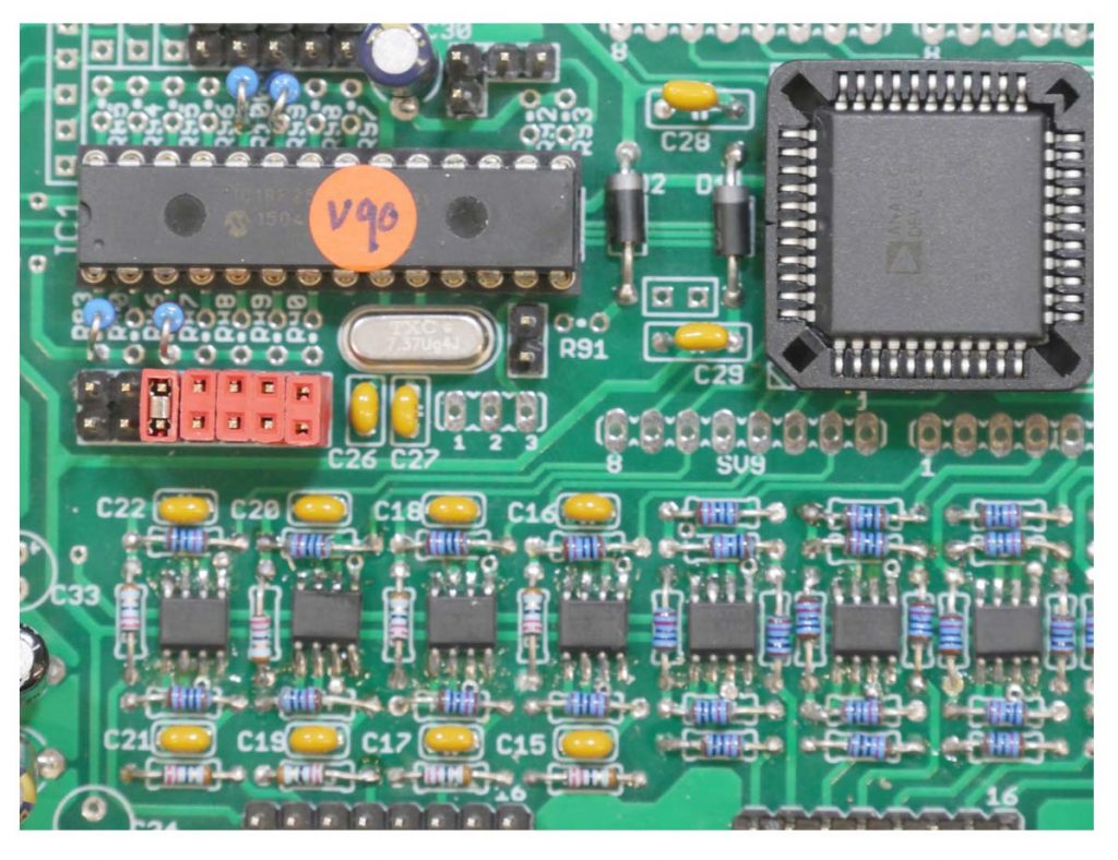
The CompLex is in fact a programmable audio-matrix. The audio-matrix and the additional audio electronics create a powerful switching and mixing platform that introduces a new way of switching.
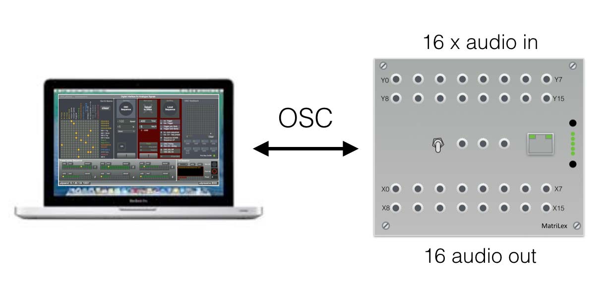
Figure 1
The interface can be directly programmed and driven by sending OSC-messages. Within this manual you will find all the basic information that you need to work and communicate with this interface. It will explain the use of the hardware and the additional software patch (Max/Msp). Since the switching speed of the CompLex is high, approx. 1,7kHz, it’s also possible to sequence through different pre-sets at high (audible) speeds. Once the 32 pre-sets are uploaded to the local memory, it can sequence through these pre-sets by means of external triggers and control voltages.
Connecting the CompLex to your computer
The first step in using the CompLex is to connect it to your computer with a standard CAT5 network cable. Of-course you can also connect to the CompLex through a regular network-router or switch, but when you make the connection for the first time, it’s easier to do it without the complexity of the network settings.
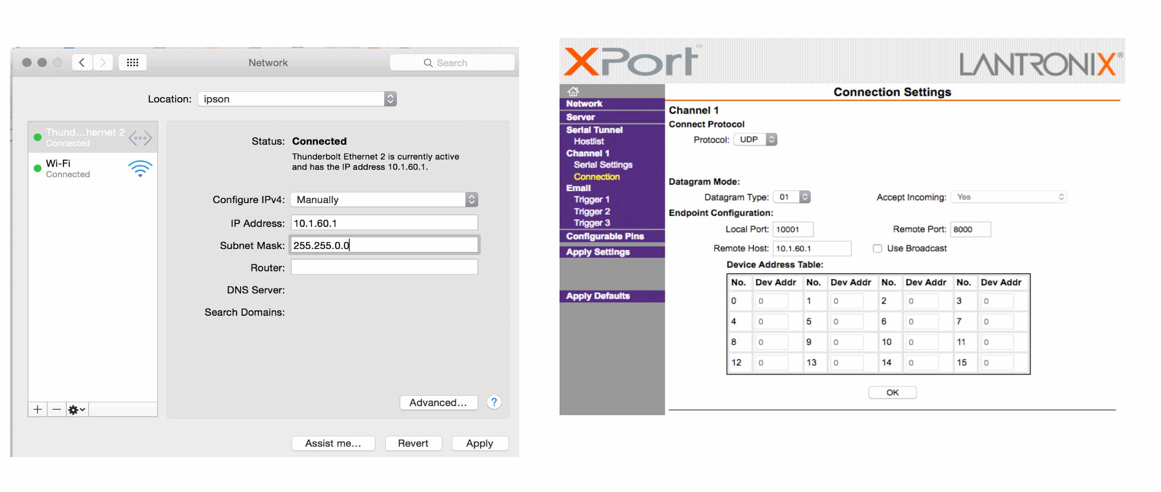
Step 1
Connect the power with the appropriate power-supply (+15V, -15V, +5V, GND). Depending on the platform you are working with (Mac or PC), you have to go to network-settings and set the ip-number of your computer to (for example) 10.1.60.1 and change the mode (configure IPv4) to ‘Manually’ (see figure 2). If you keep your settings set to ‘automatic’, your computer will ask the CompLex for an ip-address and this will not work – theCompLex cannot act like a DHCP-server – and it will not provide your computer with a valid ip-address. The network mask can be set to 255.255.0.0
Step 2
Your computer now has a static ip-number you can start a web-browser (FireFox works the best here), and type in the ip-address of the CompLex. This address is written on the back of the device. Note that the ip-addresses are all in the 10.1.60.xxx range. Please do not change the ip-address of the CompLex s itself.
Step 3
When the computer prompts for username and password, hit enter to skip. On the left side of the screen click on ‘connection’. A screen will open and you will see a layout like figure 3. In the window of ‘Remote Host’, fill in the ip-address of your computer. Your computer is the remote host. The remote port is set to 8000. The local port is set to 10001. Hit ok (this is important) to confirm and press ‘Apply settings’. The webserver of the CompLex is now rebooting and ready to be used.
Run the first test
When the onboard webserver is initialized, you can start with the first simple switch test to check the CompLex is working as expected.
Step 1
Connect an audio-signal to the input X0 and connect the input of a mixer or active loudspeaker to the output Y0. Make sure you can hear the audio when you manually connect these two signals without the matrix in between.
Step 2
Download and install the CompLex Max/patch. See figure. In the patch you can select the ip-address of the CompLex. The ip-address is written on the device itself and it has different values for every model. Fill in the IP-number of the interface in the left down corner of the figure, where it says ‘udpsend x.x.x.x’.
Step 3
Click on the matrix at the junction of X0 and Y0 and see the little dot change colour from gray to yellow. The connection is active when it is yellow. You should hear the connected audio at this point. If this is not the case, you should check the previous steps carefully and try it again.
If you are working with other software (like Super Collider or PD for example) you have to make sure you send the right OSC-messages with the right format and address tags. The format of the OSC messages is explained in the next chapter. If you work with Super Collider and you also want to make use of the monitoring feature (= the CompLex returns OSC-messages of the actual setting), you have to change the remote host port from 8000 to 57120.
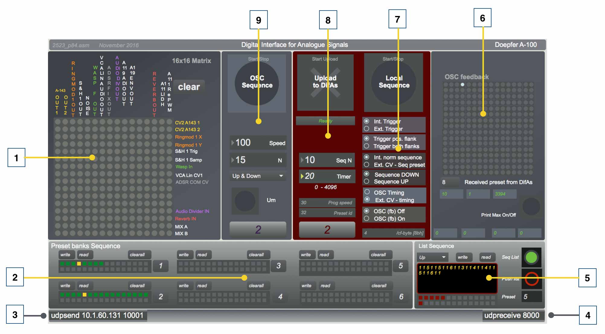
Figure 4 The example max patch version 85
- The matrix. Clicking on the gray dots wil instantly send a /pa string to the CompLex, activating this connection. If a preset is created, this preset can be stored by shift-clicking on one of the locations in [2].
- Preset banks. In this box the presets created in the matrix [1] can be stored. The preset can also be written to file or read from file. To create a physical connection, click on the right junctions in the matrix[1]. If the dots are lighting up in yellow, the connections are active and the preset can be stored. Storing a preset can be done by clicking on the right number preset box in [2] and hold down the shift key at the same time. When all presets are made and it is time to sequence through the different presets, select the right number (1-6) in box [2] and start the sequence with the start button in box [8].
- Udpsend. The computer has to send the OSC-messages to the right ip-address and port. On the left side in box[3] the ip-address and port of the CompLex has to be filled in. The port number should be 10001.
- Udpreceive. On the right side the receiving port is defined. Port 8000 will be set to receive OSC-messages from theCompLex, unless it is configured differently in the embedded webserver (see getting started).
- Sequence from lists. When you created presets, but you want to sequence through the presets in a specific order other than up/down, you should create and use lists. If the button ‘Seq List’ is active (green, or blue) the OSC sequence start/stop [9] will sequence from the list [5]. In this list presets-id’s are written from the selected bank at [2]. Before the list can be sequenced, the list should be ‘pushed’ or activated (red/black button).
- OSC visual feedback. This part of the patch shows the incoming OSC-messages from the CompLex in order to have (visual) feedback. Whether the CompLex will send OSC messages back to the computer depends on the settings of the switches or the settings of the controls explained at [6]. When the ‘print Max’ switch is turned on, the patch will print the vales that are send to the CompLex in the max-window. This option is for controlling or testing purposes only – it will slow down the total performance of the Max patch considerably.
- Configure CompLex. This part of the patch controls the configuration. The switches in this box replacing the physical switches on the different models. The biggest button on top start/stops the local sequence. The following options can be chosen going down in the patch: Internal or external trigger; Only positive or both positive and negative flank reaction for external trigger; Internal normal sequence (up/down) or ext. cv-sequence; At normal sequence up or down; The source for the speed (timing) from OSC (the patch) or from ext. Cv-speed; The last one is switching On/Off the OSC-feedback.
- Uploading presets to the CompLex This box sends the /st OSC-message in order to store the presets in local memory. When the big cross (upload to CompLex) is clicked, the active preset bank, selected at [2], will be uploaded. The rest of the variables shown in this box [7] generate a new /cf OSC-message changing the timer and the amount of presets (N) of the sequence.
- OSC-sequence. This part starts or stops the OSC-sequence. If it is active the patch sends /pa OSC-messages at variable speeds and it sequences through the selected preset-bank [2]. The speed and the amount of presets of the sequence (N) can be set as well. To offer more variation a choice of Up/Down, Pendulum (up and down) or ‘Urn’ are offered. This last option ‘Urn’ sequences through a set of presets (bank) in random order, but will use all the presets at least one time before starting with the next round.
Open Sound Control (OSC) communication.
“Open Sound Control (OSC) is a protocol for communication among computers, sound synthesizers, and other multimedia devices that are optimized for modern networking technology”
An OSC-message consists of three parts: an OSC address tag, an OSC type tag and the OSC argument(s). The communication between the computer and the CompLex is realized with OSC-messages. Figure 6 shows the generic OSC-message that is used for driving the matrix of the CompLex

Figure 6
CompLex osc-message syntax
All OSC communication in general is realized with blocks of 4 bytes. In the example above you will notice the extra ‘zero’ after the address tag ‘/pa0’. The zero (ASCII code of 0) acts as a separator between the different tags and it completes the data-string to a multiple of 4. After the definition of the type tag consisting of nine integers (9xi), also two zero’s are added to complete the multiple of 4 and be the separation between the type-tag and the OSC arguments. Both the /pa and the /st string contain in total 9 integers [v0 – v8].
For the communication with the CompLex, the address-tag (/pa in figure 6) can have three different values:
- /pa This address-tag is used if the CompLex has to activate the new matrix value instantly. Pa is an abbreviation for ‘Patch’.
- /st For storage of a preset the message should begin with /st (storage).
- /cf This shorter osc-message, consisting only of one osc-argument is used to configure the CompLex and to start and stop the sequencing.
CompLex OSC-syntax
To be able to write different matrix presets or patches to the matrix, it is absolutely necessary to write all 256 bits every time the presets changes in order to get stable behavior – that’s the setup and the design philosophy of the Analog Devices AD75019 matrix chip. If you sent ‘rondom’ values, nice chaos can be the result – but complex to analyse.

Figure 7. Bit representation of the matrix
Figure 7 shows the build-up of the OSC messages used to transfer presets, or patches, from your computer to the CompLex or vice versa. The first byte of the OSC-message, byte1, is a 32-bit integer and it holds the matrix setting from X0/Y0 to X15/Y1. The next byte (byte2) holds X0/Y2 to X15/Y3. Notice the ‘Yx’ is increasing and that every byte always contains the settings from X0-X15.
The patch osc-message (/pa)
/pa [byte 0] [byte 1] … [byte 8]
The OSC string starting with ‘/pa’ (patch) is directly activated within the CompLex when it is received. It will instantly switch On/Off the corresponding switches in the matrix. The first byte [byte0] is an extra byte which does not contain switch information, but it can hold information to configure the CompLex. Since version v85 (see chapter ‘What’s new’) this byte is empty for the /pa string. Byte 1 to byte 8 represent the 256 switches in the matrix. Check figure 7.
To better understand this way of communication, take a look at the examples below.
Example 1
If you want to switch ON the X0 and Y0, you have to set the first bit of [byte1] to 1. This is switch X0/Y0. The last bit of [byte1] represents X15/Y1. See figure 8

Figure 8 Switch ON X0/Y0
Example 2
Switching on only Y15/X15 (this is the last bit in the row of in total 256 bits):

Figure 9 Switch ON X15/Y15
Example 3
If you want to switch OFF all the connections of the matrix, you have to send all zero’s and all the matrix connections will be closed. Like this: /pa 0 0 0 0 0 0 0 0 0
Store osc-message (/st)
/st [byte 0] [byte 1] … [byte 8]
If the presets have to be stored in local-memory for later use without the computer connected, the OSC message should start with ‘/st’ (store). If the CompLex receives the OSC-message with this address-tag, the preset attached will be stored in local-memory. The first byte [byte0] determines at which location the preset will be stored into depending on the preset-id. The first byte [byte0] also contains data that determines the amount (N) of presets that will be part of the sequence. The remaining two bytes do not have a purpose (yet) and can be used for future development ideas.
 Figure 10 Storage OSC-message
Like the /pa message, [byte1] to [byte8] contain matrix switch information.
Configuration osc-message (/cf)
/cf [byte0]
The ‘/cf’ (configuration) is a single byte string and contains data to change settings or configure the mode of the CompLex. The fist versions and prototypes were supported by physical external switches to start/stop the sequence, or to make a choice between different timer sources. Since the version v85, the switches can still be used, but the configuration byte can ‘set’ or ‘reset’ the same functions. It can actually override the switch settings.
The configuration osc-message is shown below:


Figure 11 and Figure 12
Figure 11 shows the setup of the one data byte [byte0] which defines the configuration. The 8 bits on the right (the LSB bits or Least Significant Bits) contain the switch values with detailes shown in figure 12. The switch values are explained in more detail in the quick reference. The 16 bits in the middle contain the timer value. This value determines the sequence speed when the timing source is set to OSC. The 8 bits on the left (MSB or Most Significant Bits) contain the value N. This variable sets the amount of presets of a sequence.
If the CompLex is in sequence-mode (it’s running), changing the switch values will only take effect when you first stop and then start the sequence (in version v85). The one switch which always will be checked during the sequence, is the Start/Stop switch. For more detailed information about the configuration setup, check the appendix.