At some point we want to work with sensors without the use of a computer. In other words we need a circuit that is able to read the ‘weak’ voltage change of an analog resistive sensor and also is capable of adjusting the sensitivity, the gain, the dc-offset and the polarity.
This small printed circuit board (pcb) can handle 4 passive sensors and has 4 different output voltages. The pcb can be connected to the Eurorack power supply (-12V, GND, +12V and 5V). The sensor output can vary from -5V – + 10V, so it could directly drive analog modules of your modular synth.
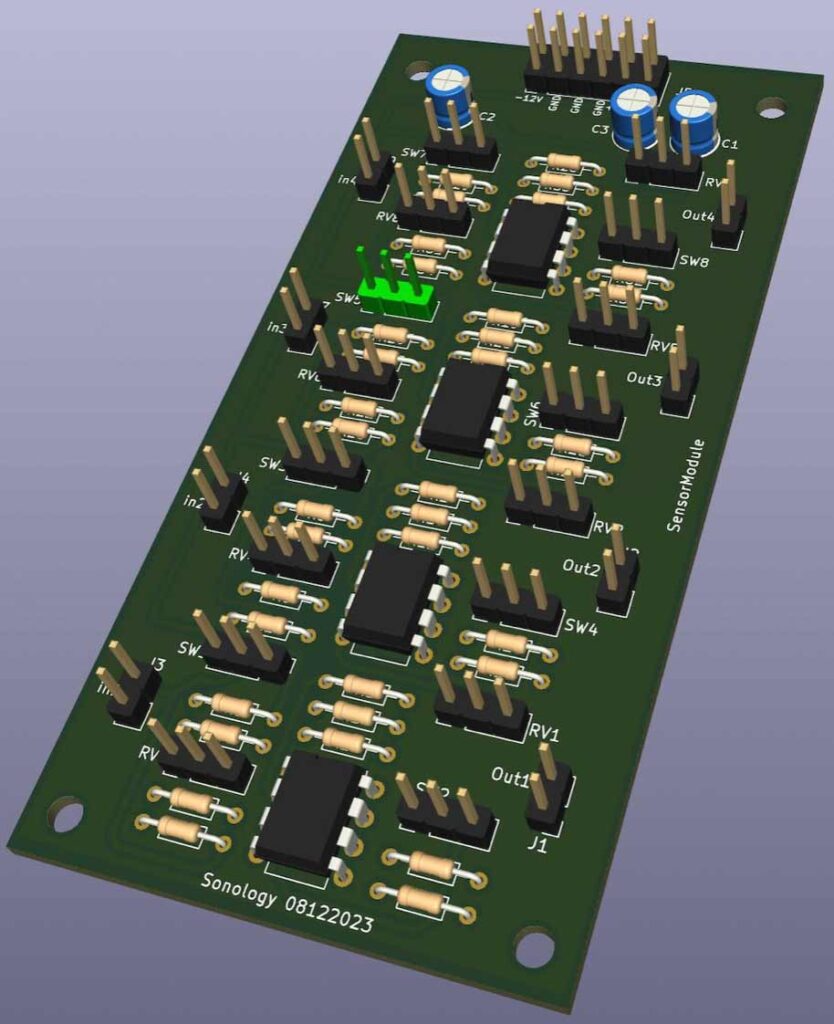
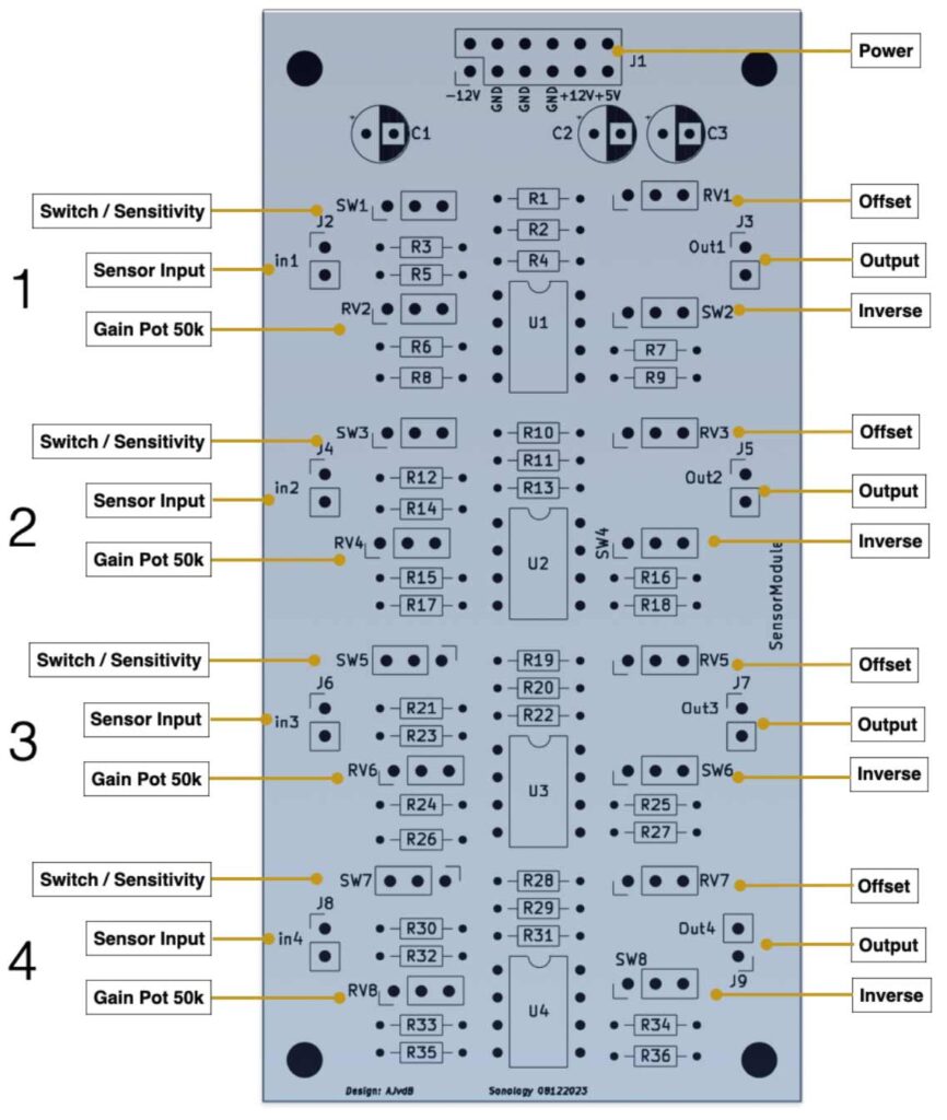
Below you will find 1/4 of the circuit (4 times the same),the pcb-layout, the component-list and a 3D impression of the PCB.
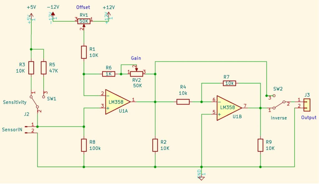
Short explanation of the circuit above:
On the left side the two resistors R3 or R5 are connected in series with the passive sensor. Since the behaviour of the sensor, or its sensistivity, depends on the value of the series resistor used, you can make a choice between different resistor values with switch SW1.
The first opamp U1A amplifies the sensor input. With potentiometer RV1 the dc-offset can be changed (the zero-point) and with potentiometer RV2 you can change the gain. With switch SW2 you can inverse the dc output voltage if needed.
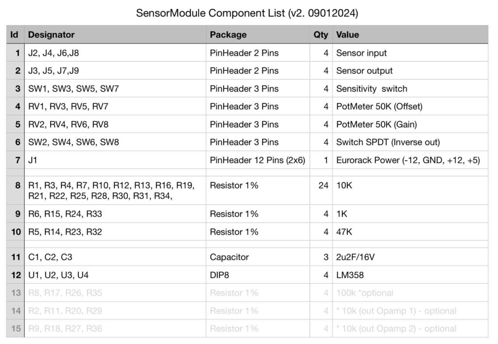
Some remarks about the table above:
1, 2 J2 – J8 are male pin headers, so you can easily solder wires to them.
3 With the switches you can select which resistor you want to connect in series with the sensor – this determines the sensitivity – you can also choose not to use this option and select one resistor that wortks well for that particular sensor. In that case you also do not have to connect a switch.
4 These pot’s adjusts the DC-offset.
5 These pot’s determine the amount of gain. Default this is set to 50K (max. 5 times amplification). You can take higher or lower values if needed (100K for example).
6 With this spdt (single pole double throw) switch (pins) you can invert the output (out / -out).