Simple mixer
When you are working with audio circuits there is always need for a mixer. Of course nowadays there are a lot of (cheap) mixing consoles available that you can use or purchase, but sometimes you just want to add (mix) some audio or cv signals within your experimental setup. If you are working with control voltages, the use of a mixer can come in handy as well.
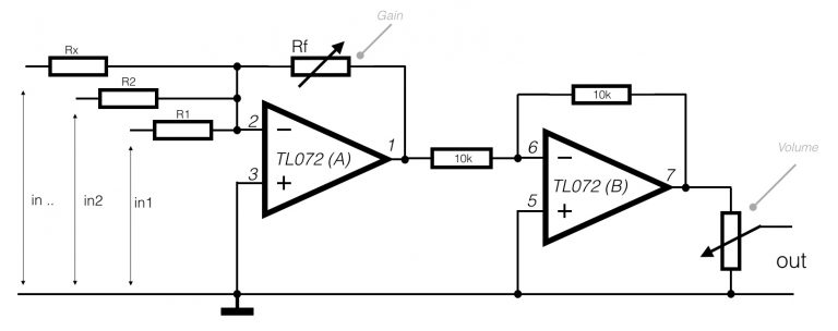
Th circuit above shows a simple setup for a mixer build around one TL072 opamp. On the left side 3 inputs, but much more inputs can be added to the same point. If you look carefully you will recognize the inverting amplifier (see opamps). The potentiometer Rf connected between the inverting input and the output of the first opamp determines the amount of gain. Because the output of the first opamp (pin 1) is 180 degrees out of phase, a second inverting amplifier is added to invert the sum of the signals again. Two resistors of 10k create an amplification of -0dB. The potentiometer on the output determines the volume of the mix. Since a TL072 is an dual opamp (two opamps in one package, A and B) you only need one 8-pin chip and a few resistors to create your own small mixer.
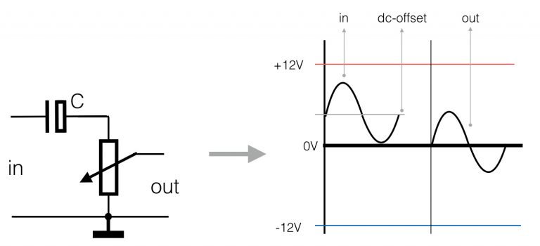
This circuit will amplify DC values as well. If you do not want to amplify DC-offsets but only pure AC signals, you have to add capacitors to the input. You can also add volume control on the separate inputs. Check the figure below. A capacitor is a blockade for DC. So only the AC-signal will flow through, resulting in an AC-signal without dc-offset.
Microphone pre-amplifier with single power-supply (battery)
A frequently asked question is how to build a microphone pre-amp with a single power-supply. When you want to use an electret microphone or a dynamic microphone, the small signal has to be amplified before it can be used in other circuits. The circuit below makes use of a TL072 opamp. Other opamps will be fine as well, whatever you have laying around.
Normally an audio circuit and especially an opamp needs a balanced power-supply like +12V, 0V and -12V. If you do not have that power available there are trick’s you can apply to amplify the signal anyway. Here’s the circuit:
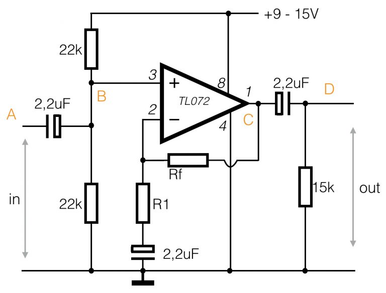
First of all you notice that the power-connections of the opamp (pin 8 and pin 4) are part of the drawing. In this case pin 4 (normally negative) is now connected to 0V (or GND). Pin 8 is connected to the plus power which can vary from 5 – 18V max. The circuit is a standard non inverting amplifier (check opamp page)with some extra resistors and capacitors to perform the ‘trick’. Take a look at the graph below and the letters in the circuit:
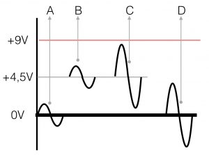
A: This is the small input signal form the microphone. It’s relative to 0V.
B: The two resistors of 22k create a voltage divider (see basics) giving the + input of the opamp an DC offset of +4,5V. Because a capacitor blocks DC, only the AC-signal (from the microphone) will be ‘super imposed’ on the DC-offset. Superimposed means it is placed on top of the DC-voltage.
C: The output of the opamp will give the amplified signal, again on top of +4,5V. The amount of amplification is determined by Rf / R1. At this point you have to be careful with the amount of amplification, because the ‘overhead’ (the space you have) is only 0-9V (or virtually (-4,5V – +4,5V).
D: To get rid of the DC-offset, we insert a capacitor again and we add a resistor of 15k to ‘anchor’ the signal back to 0V. In this way the signal is ready to be transferred to the next stage or circuit.
So within this circuit we create a so called ‘virtual ground’ of +4,5V. If you apply this to your circuits, you have to always use capacitors to separate the DC-values form your AC-signal.
Little power amplifier (with the LM386)
If you want to connect a speaker to your circuit to hear the results of the experiments, you need an amplifier in order to do so. A speaker, in general 4 – 8 Ohms, draws quiet some current and needs to be fed by an amplifier which is capable of delivering this current. The circuit shown below is the simplest solution to have a (small) speaker making sounds. The LM386 chip is specially designed to be an ‘power’ amplifier. The LM386 is a 8-pin package (like the TL072).
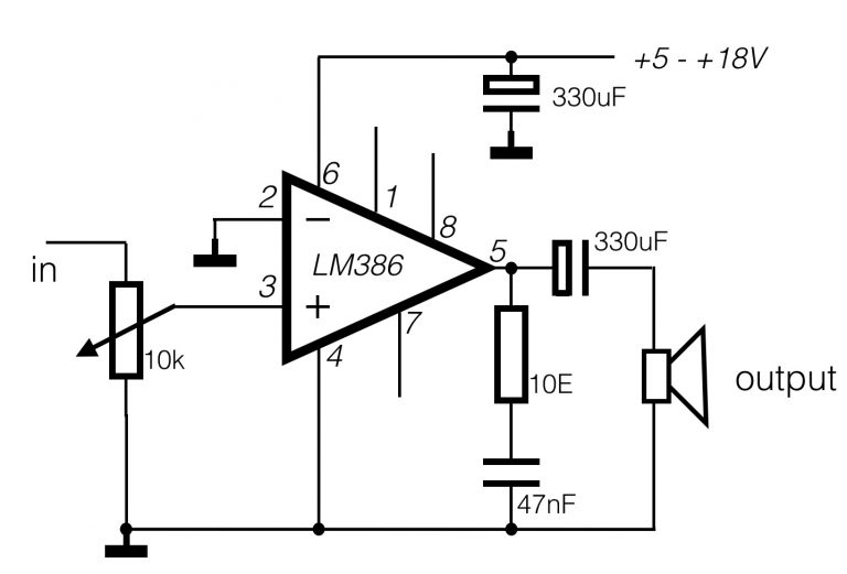 The circuit drawn above is the standard application of the LM386. You can find variations of this circuit in the data-sheet of the LM386. The audio input is attenuated with a potentiometer of 10k – creating the volume. As you will see if you look at the data-sheet, pin 1 and pin 8 can be used to increase the gain. If nothing is connected (like the circuit above) the gain is 20x. In this default circuit design, pin7 (bypass) is left unconnected.
What is not in de application note, but absolutely necessary, is the capacitor of 330uF parallel to the power (pin 6). This capacitor avoids annoying buzz.
On the output you see a HF-cut filter (10Ohms and 47nF) to avoid oscillation of the amplifier. Any small speaker with an impedance between 4 – 8 Ohms can be connected. Do not expect too much from this small amplifier – it’s a cheap and fun solution for making your experiments audible.