In audio world it is nice to have some oscillators around to test audio-equipment like amplifiers, mixers and filters. Oscillators are also great musical devices though! I will show some very interesting sounding simple to build oscillators. When these simple oscillators are combined with sensor-values, some great sounds can be revealed.
The principle of an oscillator is feedback. Think of a microphone that is too near to the speaker – it will make a harsh high beeping tone. This is what we call feedback. In general we want to avoid feedback, but in case of an oscillator design it’s a great feature.
The most simple oscillator you can make is one based upon a ‘Schmitt trigger’ (digital) port. There are several chips available that have this function like: HEF40106, or CD40106, 7413, 7414 and a lot more.
In this part I will use the 40106 chip. This is a hex schmitt-trigger inverter chip – hex means there are in total 6 of those ports embedded in one physical chip (housing).
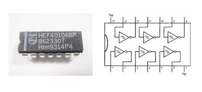
A schmitt trigger port has two thresholds upon which it will change its state. If the input of this inverter port goes above the upper threshold (say 4,5V), the output will change value, in this case will switch to zero – since it’s an inverter. If input goes below the lower threshold-value (say 2,5V), the output will change from “0” to “1” (0 – 5V).
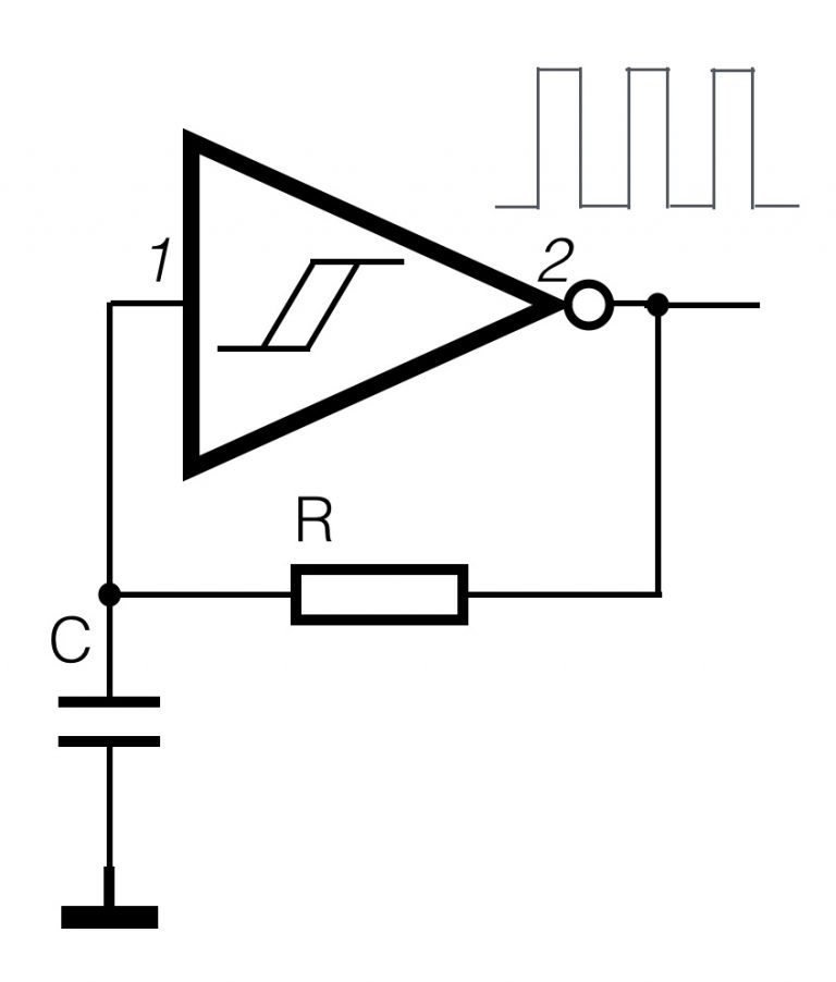
The circuit on the the right shows the simplest setup of an oscillator. How does that work? Pin 2 (the output of the inverter port) is connected to the input of the same port through a resistor R. The input is also connected to a capacitor.
– Suppose the input at pin 1 is 0V (in case of start-up for example), the output will be ‘high’. If the power-supply of the chip is (say) 9V, the output is also 9V.
– At that moment the voltage at pin 2 is higher than pin 1, the current will flow through the resistor R, into the capacitor C.
– The value of the voltage parallel to the capacitor will ‘slowly’ rise above the upper threshold and the output of the invertor will switch from 9V to 0V. Now the capacitor will discharge through the resistor, until the value of the input (pin 1) will drop below the lower threshold – the output goes ‘high’ again (it will be 9V).
– We are back at the beginning and the cycle will keep on going. It will resonate its own static frequency. The frequency depends on the value of the capacitor and the resistor. They determine the ‘speed’ of the process. The bigger the capacitor and the resistor are, the slower the system lower frequency).
If you use a resistor that can change value, like a potentiometer or a sensor (Force Sensing Resistor), the frequency of the oscillator will change up/down. The more interesting results will start when you combine more ports together.
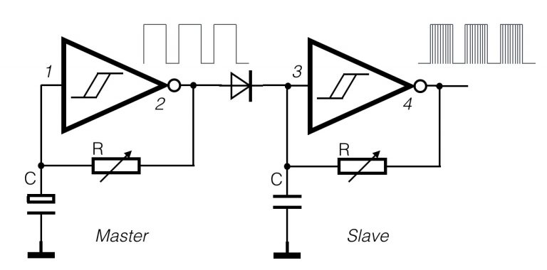
The circuit shown is called a master-slave combination. The ‘ slave’ is only working when the output of the ‘master’ is ‘high’, due to the diode.
The capacitor and the resistor of the master have higher values and will resonate on a lower frequency. The ‘slave’ has smaller values and is oscillating on a higher frequency. On pin 4, the output of the slave, the ‘master envelope’ is filled with the signal of the slave. Both resistor symbols do have an small arrow. This means you can use ANY variable resistor you want (LDR, FSR, Potentiometer, Digital potmeter, NTC, …).
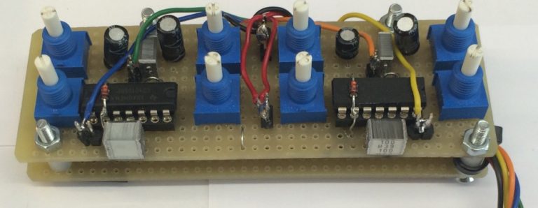
An example of an circuit that consists of 4 master-slave combinations:
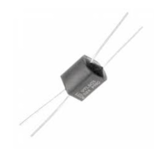
To make this oscillator suitable for control voltage, a nice way to do this is with a ‘vactrol’. This is a combination of a LED (light emitting diode) and a LDR (light dependent resistor) in one package.
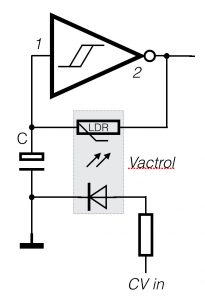
When the CV is going form 0V to (say) 5V, the light intensity of the internal LED will increase. Since the LED is coupled to a resistor that changes value when the light is more/less bright, a coupling is created
Oscillator with the NE555
The NE555 is a very popular timer chip, often used in electronic circuits. That doesn’t mean it an ideal chip, but it is a very easy chip to create wave-shapes of different frequencies. You only need to connect some resistors (R) and capacitors (C) en there you go, it will run. I do not want to explain al the in’s and out’s of the chip, because if you “Google” the NE555, you will find more than enough information to tweak your design. Take a look at the circuit below:
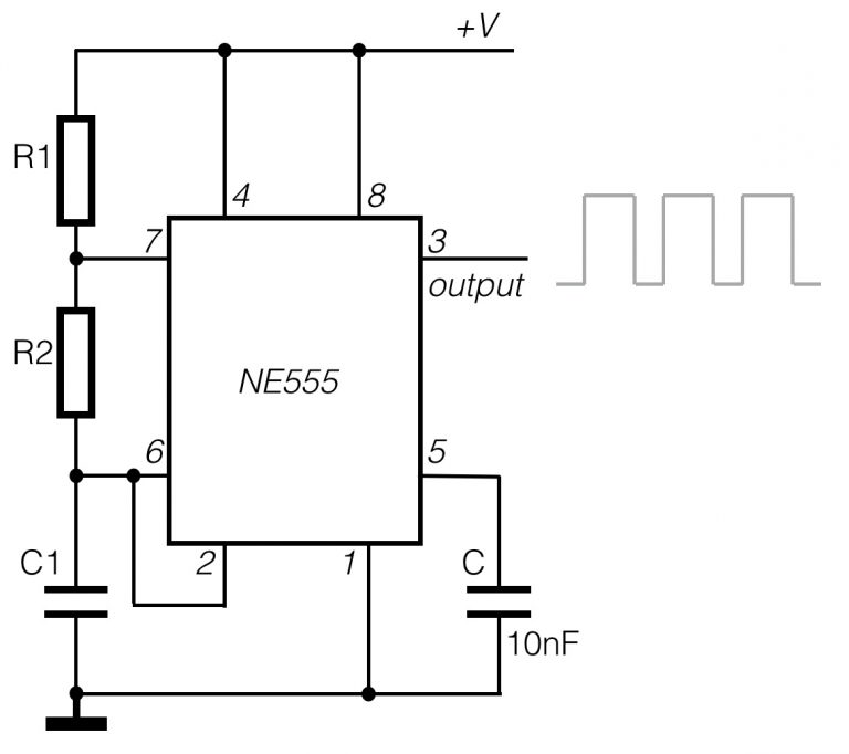
The NE555 is (again) a 8-pin chip. The resistors R1, R2 and C1 determine the frequency and duty cycle of the signal on the output.
If R1=R2=10K and the capacitor C1 = 47uF, the frequency will be around 1kHz and the duty-cycle around 66%. Take a look at think link to calculate other values.
You can exchange the resistors for potentiometers and change the frequency / duty-cycle on the fly. Just try it out!
Sine-wave oscillator with the XR2206
There always seems to be ‘need’ for relative simple sine-wave generator circuits. Well, here I have a simple one, with a relative good quality sine-wave. To create a ‘perfect’ sine-wave is quiet difficult with analogue electronics.
The chip that is used in this circuit below is the XR-2206. A quote from the data-sheet: “The XR-2206 is a monolithic function generator integrated circuit capable of producing high quality sine,square, triangle, ramp, and pulse waveforms of high-stability and accuracy“.
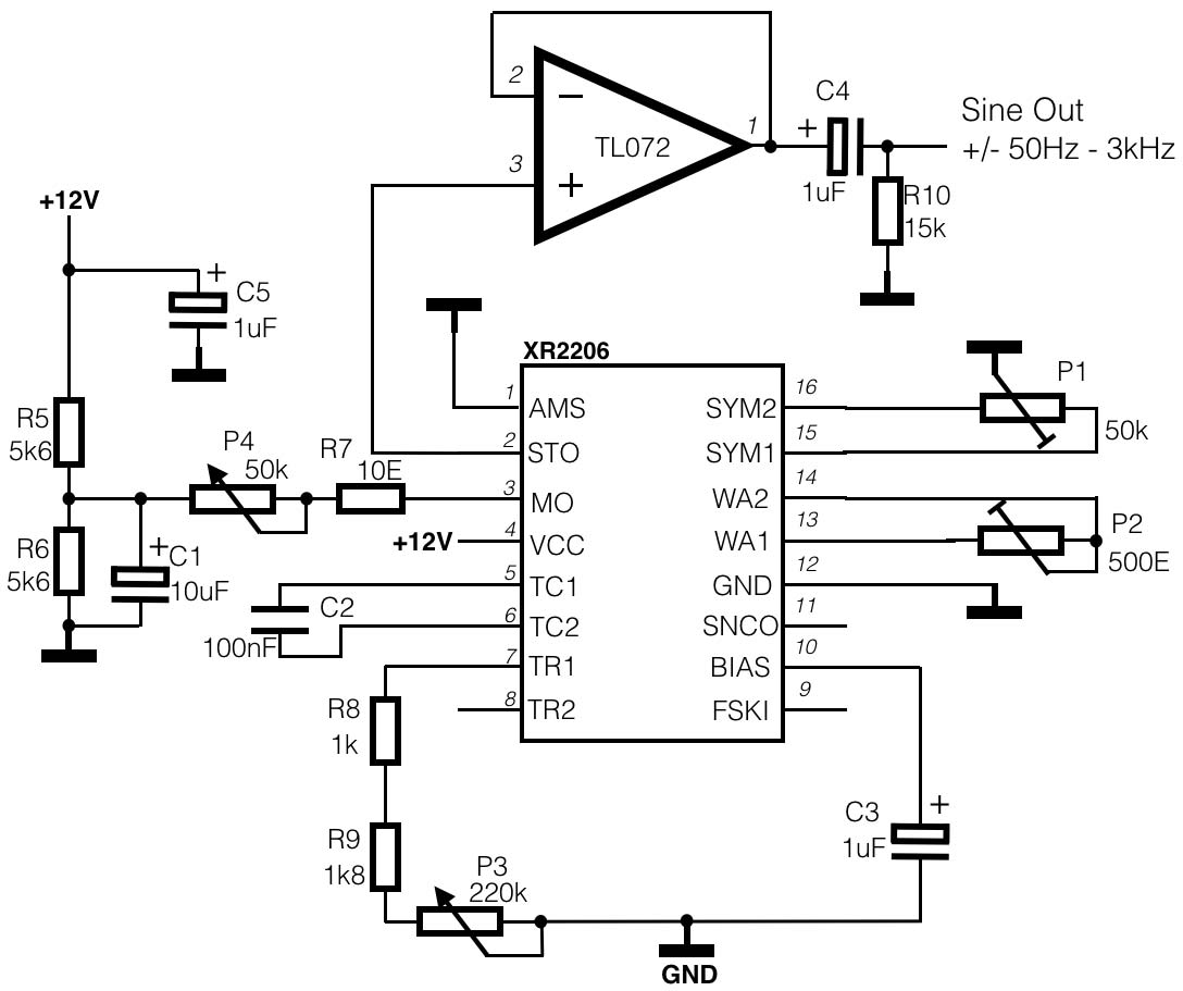
The circuit shows just one application out of many possibilities. It is an adjustable sine-wave generator within the range from (more or less) 50Hz – 3kHz. Potentiometer P3 is used to change the frequency (or pitch) and P4 changes the output amplitude. If you want to change the frequency range, you have to adjust resistor values, R8, R9 and P3 in combination with C2. The symmetry of the sine-wave can be adjusted with trim-pots P1 and P2. This example is copied from one of the application notes in the data-sheet. For more information, please take a look here
The opamp is used to buffer the output and (with the RC-combination) remove the DC-component of the signal. The XR-2206 chip is still for sale, but it looks like the manufacturer (Exar) stopped with the production. While writing this article, I still found the chip for sale at: www.reichelt.com.
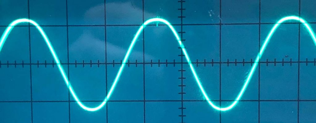
Below a photo of the actual sine-wave produced with the XR2206.