On this page you will find additional information on how the B&K Vocoder installed in the VSC (Voltage Controlled Studio) can be used. The B&K Vocoder is a combination of two Bruel en Kjear Band Pass Filters (Type 1615) and two audio matrices. For the technical specifications and the complete design, please check this link
The device:
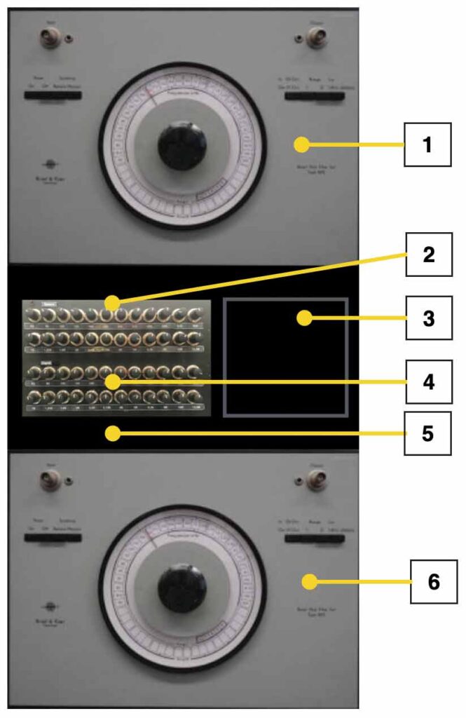
- This is the 1st bandpass Filter.
- The whole black box in the middle holds all the electronics of the vocoder. The upper 24 pots change the signal strenght of the linked frequency (24 bands).
- This is the display. For now it is not in use.
- The lower 24 pots define the signal strength of the second signal – also chopped into 24 different frequencies.
- The few buttons below are meant to drive the display. They are not in use yet.
- The second bandpass filter
The following frequencies of the spectrum are used:
63Hz, 80Hz, 100Hz, 125Hz, 160Hz, 200Hz, 250Hz, 315Hz, 400Hz, 500Hz, 630Hz, 800Hz, 1000Hz, 1250Hz, 1600Hz, 2000Hz, 2500Hz, 3150Hz, 4000Hz, 5000Hz, 6300Hz, 8000Hz, 10kHz, 12.5kHz.
The design idea of the Vocoder is drawn below. The first audio input (referred to as the speech input) is divided into 24 different frequency bands. These 24 freqencies are then conditioned (buffered and amplified with VCA’s) before being de-modulated. The result of demodulation is that every freqency is converted into a “envelope or dc-value” that represents the energy of that particualr frequency band. These 24 ‘envelopes’ are connected to the input of the first 24 x 24 matrix (/pa).
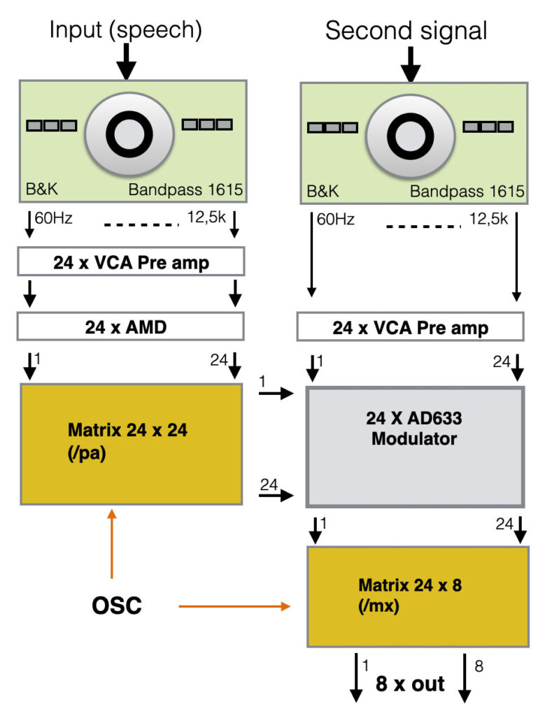
The second signal (this can be any signal, for example noise) is also divided into the same 24 frequency bands and conditioned (amplified with VCA’s and buffered). These resulting 24 signals are the source input for the 24 independing modulators, designed around the AD633 chip. This chip is an analogue multiplier with two seperate inputs X and Y.
With the matrix (quad complex) can be determined which frequency of the 24 bands “envelope or dc-value” from signal 1 is now used to be multiplied with the second signal. Driving the right OSC-maessage into the Vocoder will adjust the Matrix on the fly. Take a look at the examples below:
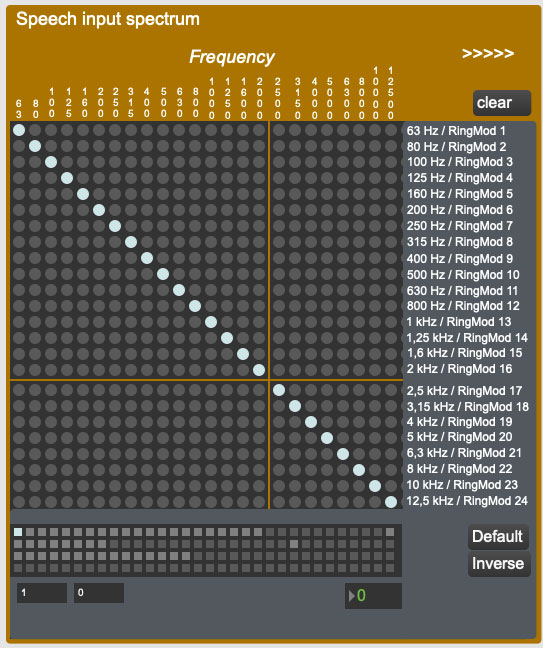
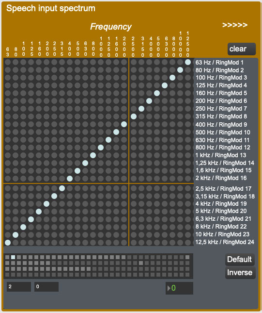
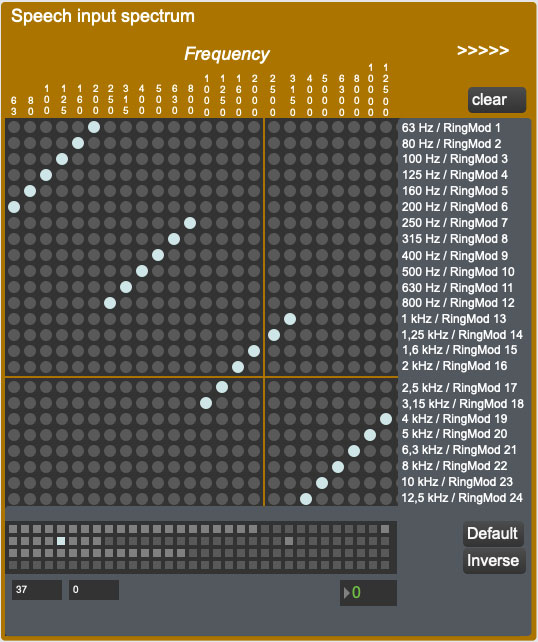
In the default setting the frequency bands are ‘1 to 1″ distributed. So the 1kHz of the speech input, will modulate the 1kHz of the second signal. If you switch to inverse setting (middle picture) the energy levels (demodulated signals from the speech) for low frequencies are now used to be the source drive for the high frequencies. You can choose any conversion you want by configuring the matrix.
The Vocoder Max/Msp patch
On the computer (iMAc) of the VCS studio a test patch is installed to drive the Vocoder. This Max.Msp patch does nothing more then sending out the right OSC-messages to switch the matrix. The patch can also be downloaded here.
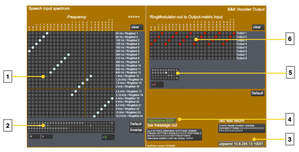
- The 24 x 24 matrix with on the top the 24 inputs, coming from the split demodulated speech input. By clicking on the matrix you van make a connection between the in- and output. So with this matrix-object you can configure which frequency of speech input 1 will be the source for the ‘split’ freqencies of signal 2
- This is a preset object. If you found a nice setting of the matrix, you can click on one grey dot, while keeping the SHIFT button pressed. The preset is now stored.
- This is the IP-addres of the Vocoder.
- If the Vocoder could send information back to the patch (which it does not at this time – I used it for testing reasons), it will be received on port 8000.
- The same as number 2. A preset object that can store the presets of the output matrix.
- The output matrix. The 24 inputs on top are the result of the modulation output of the first matrix. With the output matrix you can determine which result goes to which output. The Vocoder has 8 seperate outputs.
OSC-messages.
The Vocoder can be driven with two different OSC-messages, one driving the 24×24 matrix and the other the output matrix. Since the Vocoder has two extended matrices onboard (quad complex and dual complex), more detailed inforamtion about the setup of the OSC-strings can be found here.
Write 24 x 24 vocoder patch: /pa [byte 0][byte 1] ... [byte 31]
Write 32 x 16 output patch: /mx [byte 0][byte 1] ... [byte 31]
The B&K Vocoder has IP address:: 10.9.234.13