Some basics of electronics
To be able to understand a little bit more about electronics and the circuits that are shown on this or other websites, it is actually inevitable to understand Ohm’s law – it makes live a bit easier. 😉 You have to understand what happens with the current, the voltage and the resistance. All these three variables are linked and make part of ‘Ohms Law’.
In formula: U = I * R (the voltage [V] is a product of the current {A] and the resistance [Ohm])
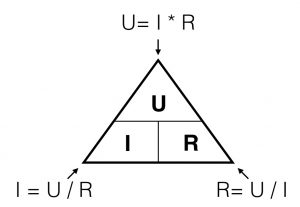 A graphical representation of this formula: when you look to the triangle from one of the three angles, you ‘see’ the formula’s for every variable. If you look from the top you ‘see’ U = I*R. Looking from the left corner beneath, you ‘see’ I=U/R.
In other words: the higher the value of the resistor, the lower the current given a constant voltage (the battery). If the resistance is 0 Ohm, we call this a short-circuit. A short circuit will result in a undefined value (too high) of the current (dividing by zero is not possible).
Example: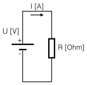
suppose you have a battery of 9V. If you connect a resistor of 1KOhm (=1000 Ohm) parallel, the resulting current will be:
I = (U / R) = 9 / 1000 = 9 mA = 0,009 Ampere (A) (9 mili Amp)
Be aware of the values that you use with these kind of calculations. Try to make use of the ‘engineering-values’ and avoid shifting comma’s. See the figure below.
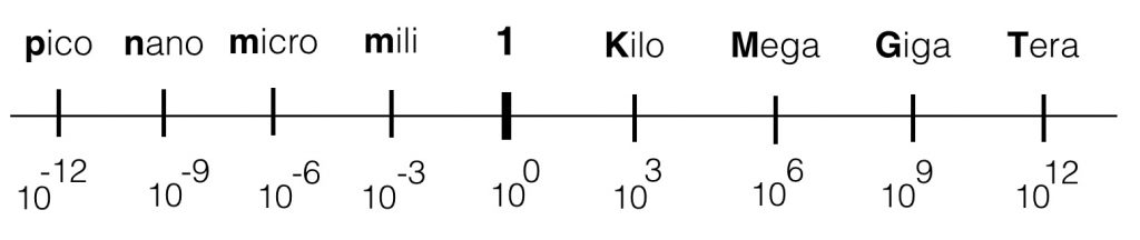
Within electronics (especially the audio ‘world’), the values we use will vary from Tera (= 1000000000000) or 10^12 ( a one with 12 zero’s) to pico: 0,000000000001. The engineering values always take steps of ‘3’ digits, in order to keep the notation clean.
Series and parallel
Resistors can be placed in series and in parallel.
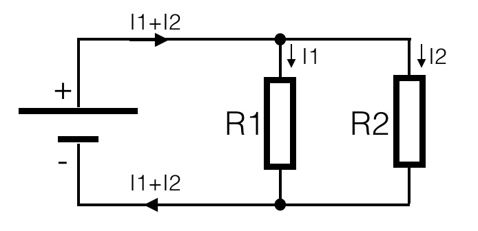 If resistors are placed in parallel they divide the current in equivalent parts. The voltage parallel to the two resistors is for both resistors the same. It is one electrical node. The current however is divided into two separate current flows. See the figure.
If resistors are placed in series, we call this a voltage divider. It actually divides the voltage applied to the series resistors in equivalent parts. In the figure you see two resistors R1 and R2 connected in series. The current is determined by the total resistance (R1+R2) and is the same in the whole loop. The symbol that shows ‘in’ is a battery, but it can be any signal source.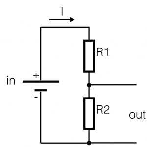
If both R1 and R2 have the same value (R1=R2), the value of the output (out) will be exactly half of the value of the input. In other words, this circuit with two series-resistors is called a voltage divider. If resistor R2 is bigger in value than R1, the voltage parallel to R2 (=out) will be proportional higher. The values are proportional to the resistors. This can be written down like this:
out = ((R2 / (R1+ R2) * in)
Simple filters
Working with electronic circuits involves the use of filters. You want to be able to get rid of unwanted signals (disturbances) or you are only interested in a particular part of the frequency spectrum of a given signal. To be able to ‘filter’ the signals, you make use of filters. Filters can be divided into two main groups: passive filters and active filters. A passive filter is constructed with only passive components (capacitor, resistor, coil) whereas an active filter has an active component (semiconductor) added to the design as well. We will start with passive filters.
Passive filters
Te most common passive filters are HPF and LPF (high pass and low pass). In order to understand how they work we start again with the voltage divider as explained above.
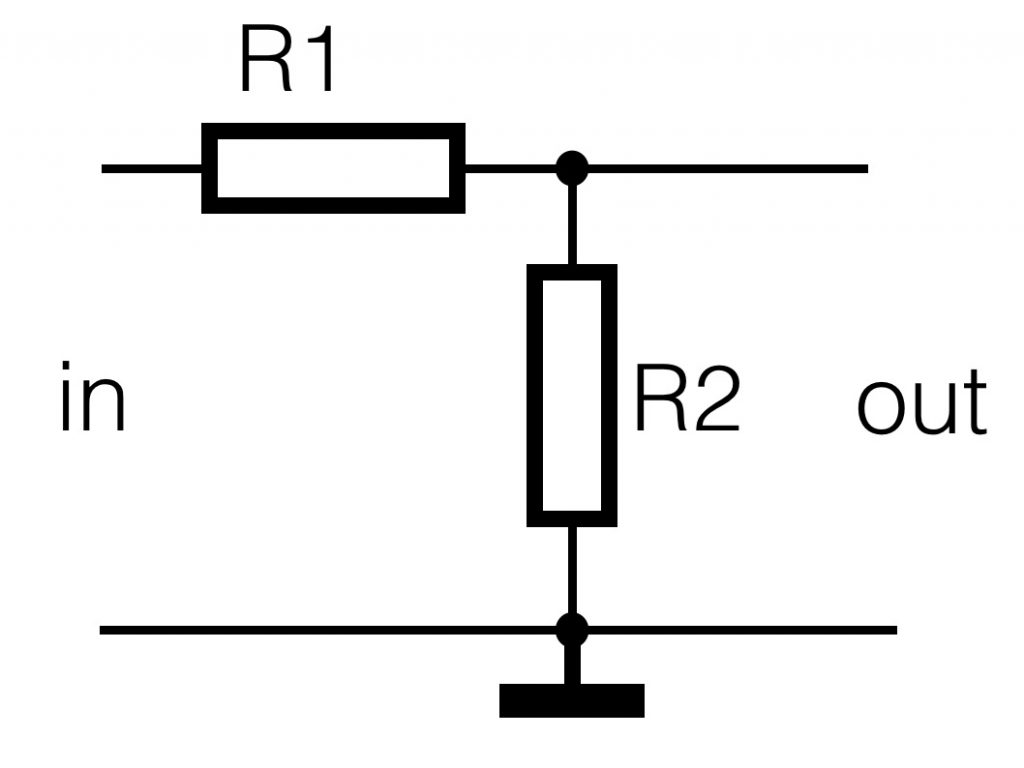
There’s no physical difference with the voltage divider above, the circuit is only drawn different. What we have to remember is: the higher the resistance of R2, the higher the output ‘out’. And the smaller the value of R2, the smaller the value of ‘out.
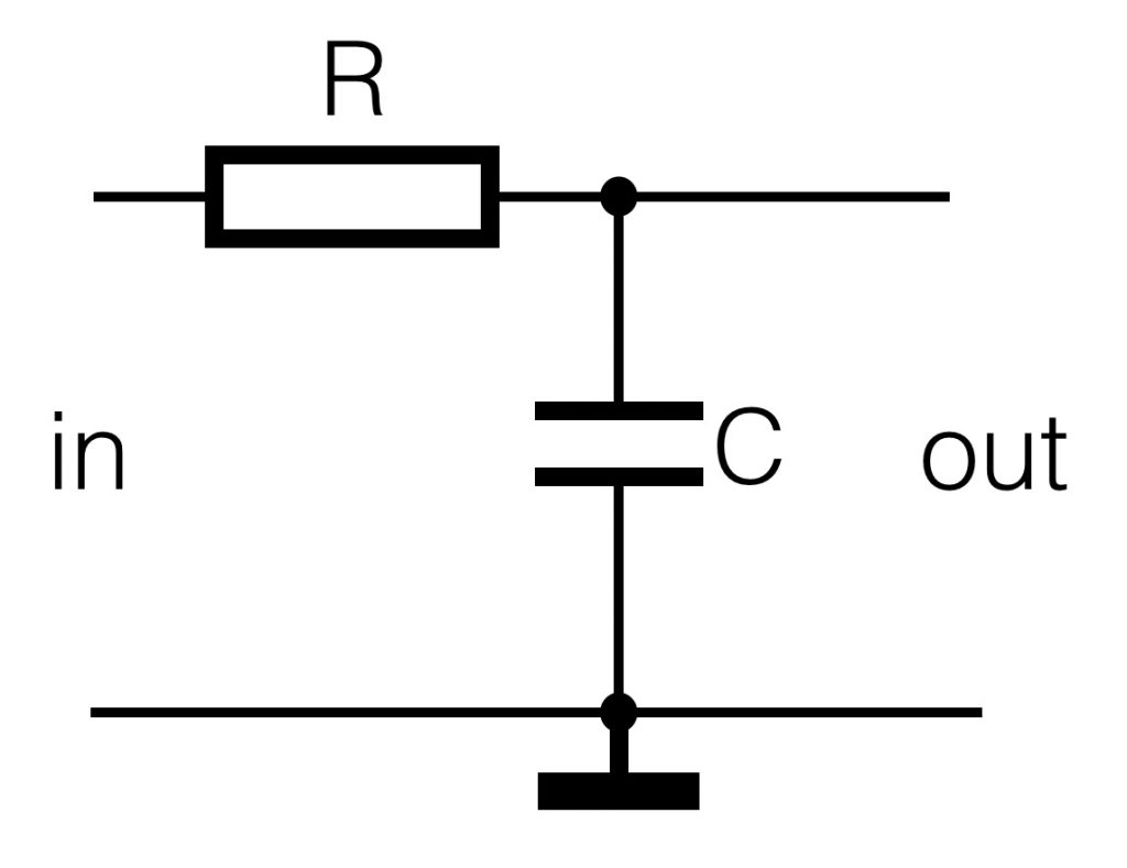 Now we replace R2 for a capacitor. A capacitor does not conduct DC current, it blocks it. So for DC values (the frequency is zero) the capacitor is an infinite high resistor. The higher the frequency on the input, the more the capacitor will start to conduct (it’s resistance will get smaller). The R and the C determine the resonance frequency or the -3dB frequency. This is the frequency at which the output of the filter is half (= -3dB) of the value of the input. This means the higher the frequency, the lower the output will be. We created a LowPass filter.
 The -3dB frequency: f (-3dB)= ( 1 / ( 2 * pi * R * C ))
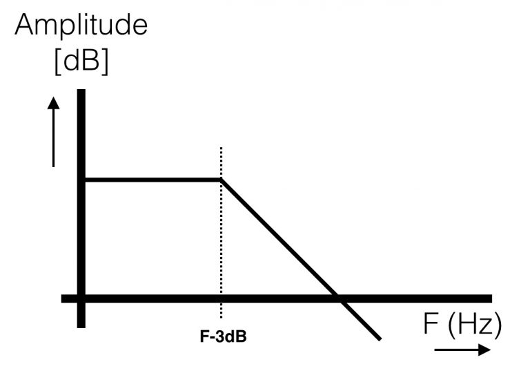
The (very rough!) graph of a lowpass filter:
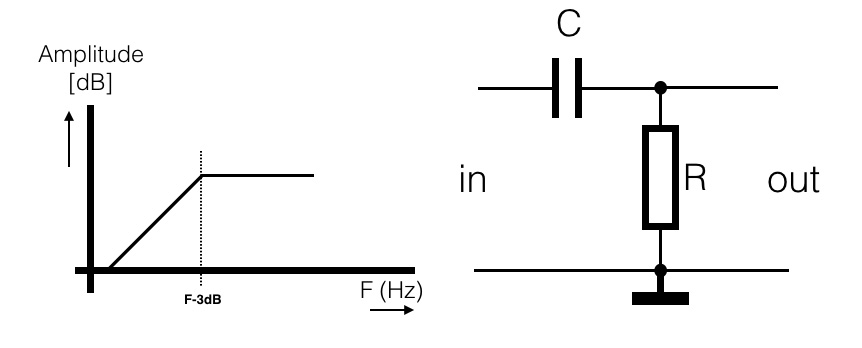
If we switch the capacitor and the resistor from position, the opposite circuit will appear:
a High Pass filter. Also here the capacitor is a blockade for DC. In this case the output will be ‘zero’ at DC (or 0Hz). The higher the frequency the more output.
More information and a more mathematical approach to this subject can be found here: