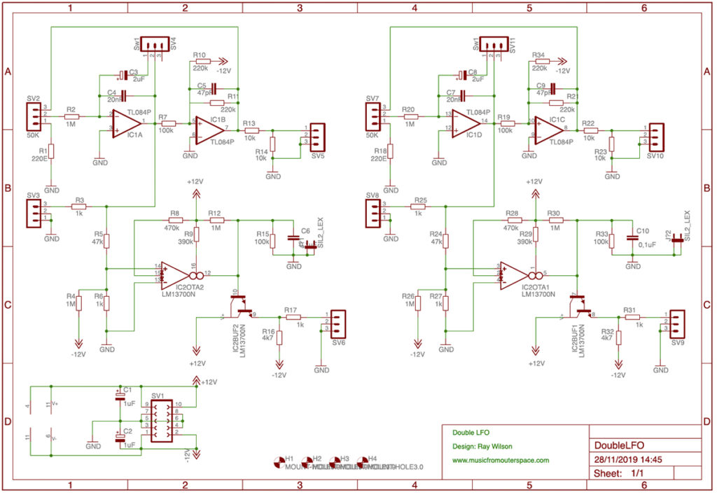
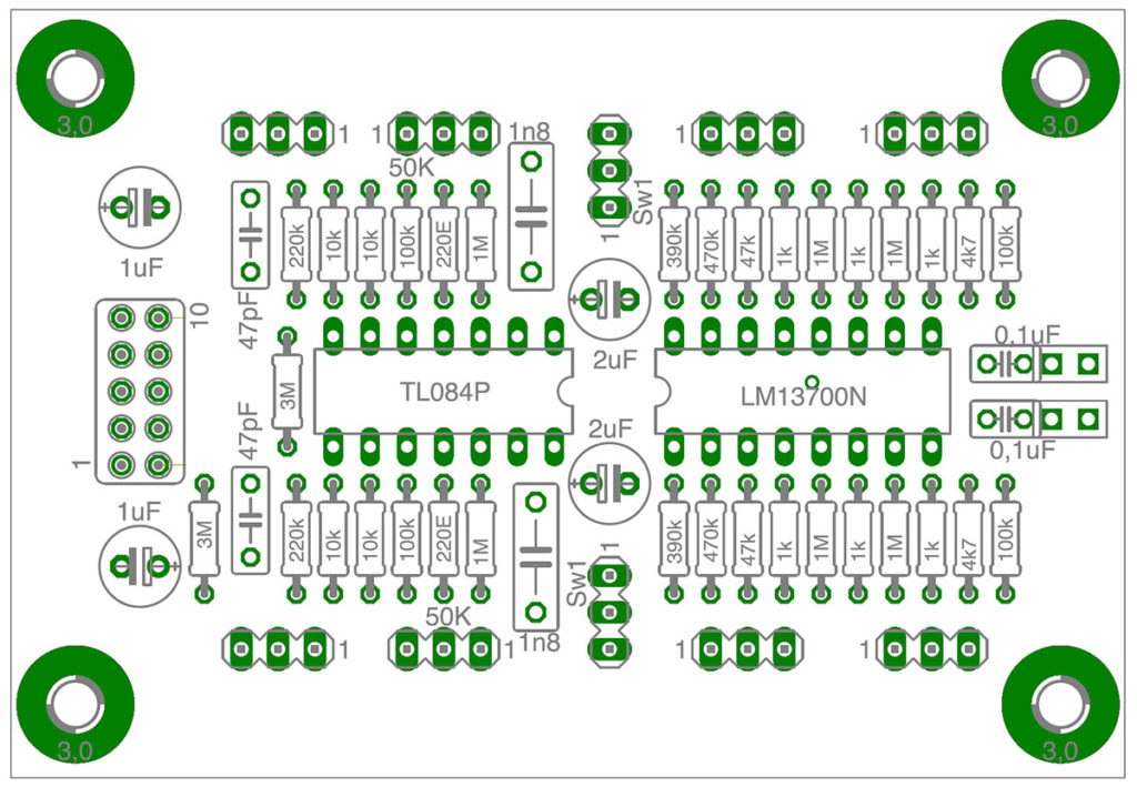
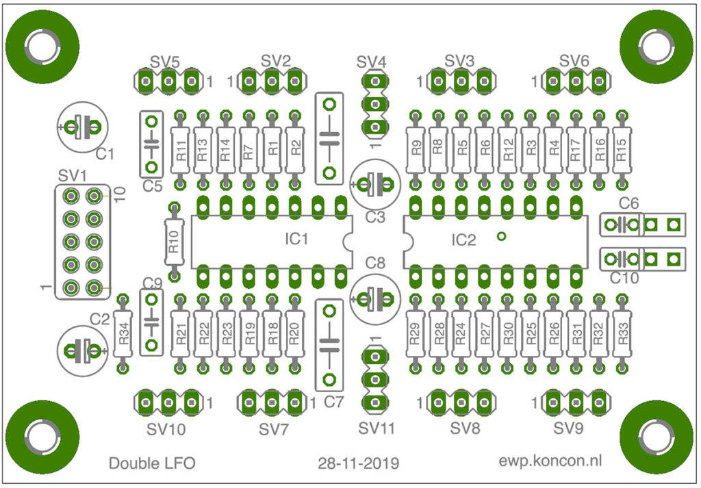
As a follow-up of the small LFO (see last post), I designed a Printed Circuit Board (PCB) of the LFO, so it is easier to make this circuit for anybody who is interested. Since the LM13700 chip has two OTA’s onboard (2 x Operational Transconductance Amplifier) I also created two LFO’s. (like the design made by Ray Wilson).
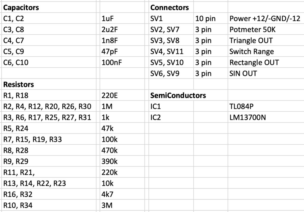
One LFO has 3 outputs: rectangle, triangle and sine-wave. With a potentiometer of 50K the frequency can be changed. The switch is added to be able to change the frequency range.
The circuit takes +12V, GND and -12V. It uses the Eurorack standard power-supply connection. Please consider that this is a very basic LFO circuit and notice the amplitudes of the output signal are not constant over the frequency range. But still, a great LFO!