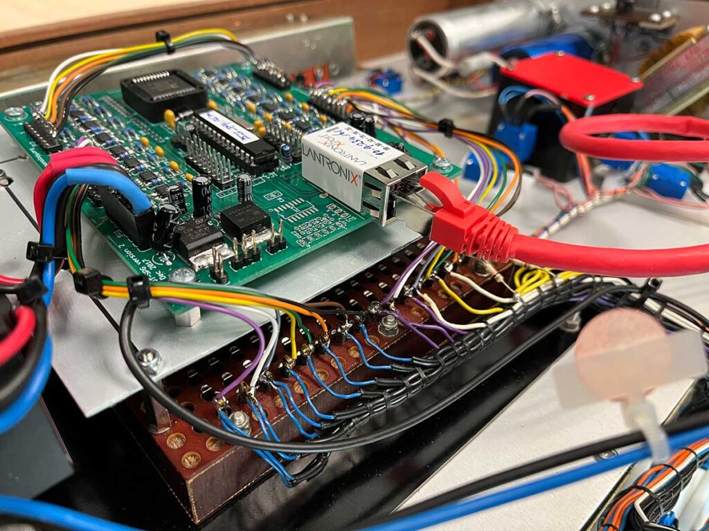
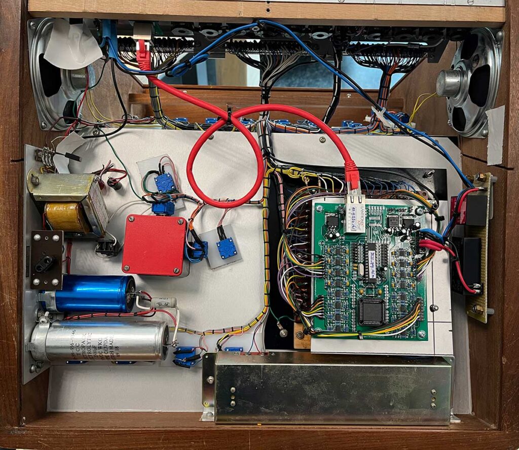
The Institute of Sonology in Den Haag purchased two VCS-3 synths back in the eighties . Over the years lots of students used the synths for their compositions and that shows. They are used! Both of them are still fully operational and in one of the machines I embedded a OSC matrix.
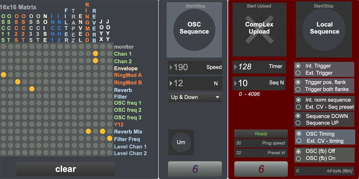
Parallel to the analog physical matrix on the outside (where the small pins make connections between the onboard modules), the OSC matrix is mounted. Great thing is that it has exactly 16 inputs and 16 outputs – the exact fit of the OSC-matrix.
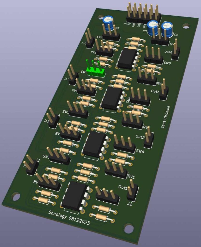
This is a 4 channel dc-amplifier for analogue sensors to be connected. The output can vary from -10 / +10.
At some point we want to work with sensors without the use of a computer. In other words we need a circuit that is able to read the ‘weak’ voltage change of an analog resistive sensor and also is capable of adjusting the sensitivity, the gain, the dc-offset and the polarity.
This small printed circuit board (pcb) can handle 4 passive sensors and has 4 different output voltages. The pcb can be connected to the Eurorack power supply (-12V, GND, +12V and 5V). The sensor output can vary from -5V – + 10V, so it could directly drive analog modules of your modular synth.
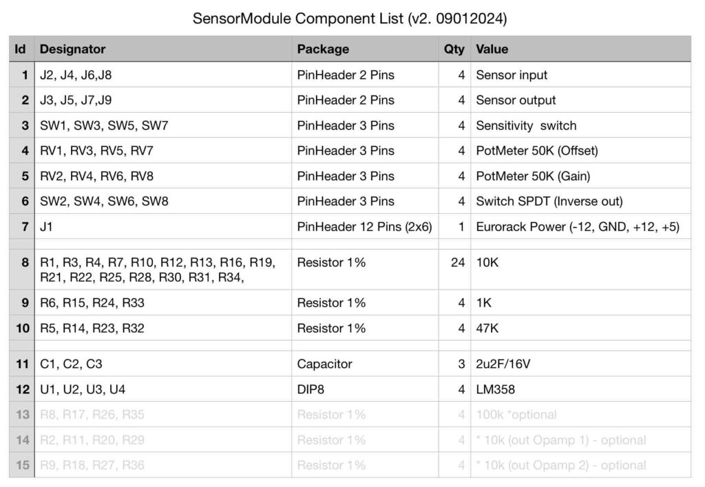
Below you will find 1/4 of the circuit (4 times the same),the pcb-layout, the component-list and a 3D impression of the PCB.
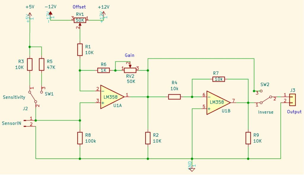
1/4 of the circuit
Short explanation of the circuit above: On the left side the two resistors R3 or R5 are connected in series with the passive sensor. Since the behaviour of the sensor, or its sensistivity, depends on the value of the series resistor used, you can make a choice between different resistor values with switch SW1.
The first opamp U1A amplifies the sensor input. With potentiometer RV1 the dc-offset can be changed (the zero-point) and with potentiometer RV2 you can change the gain. With switch SW2 you can inverse the dc output voltage if needed.
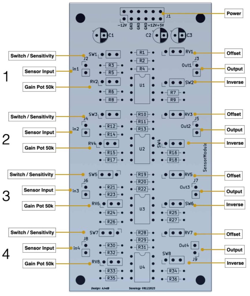
PCB Layout
Some remarks about the table above:
1, 2 J2 – J8 are male pin headers, so you can easily solder wires to them. 3 With the switches you can select which resistor you want to connect in series with the sensor – this determines the sensitivity – you can also choose not to use this option and select one resistor that wortks well for that particular sensor. In that case you also do not have to connect a switch. 4 These pot’s adjusts the DC-offset. 5 These pot’s determine the amount of gain. Default this is set to 50K (max. 5 times amplification). You can take higher or lower values if needed (100K for example). 6 With this spdt (single pole double throw) switch (pins) you can invert the output (out / -out).
After a long time of not being busy with real electronics due to the move of the whole orgnisation to the new building – it has a hugh impact – I slowly see more time for being busy with my core activities: make new instruments and electronics.
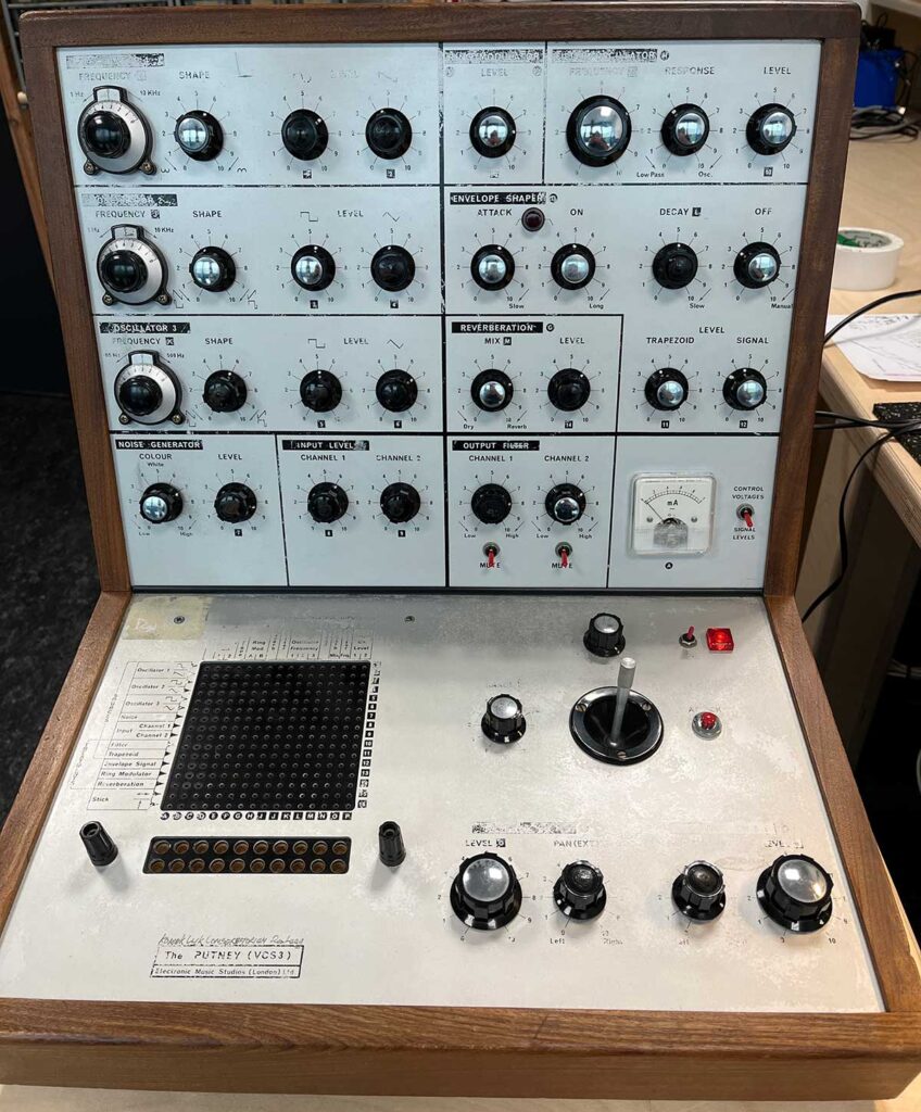
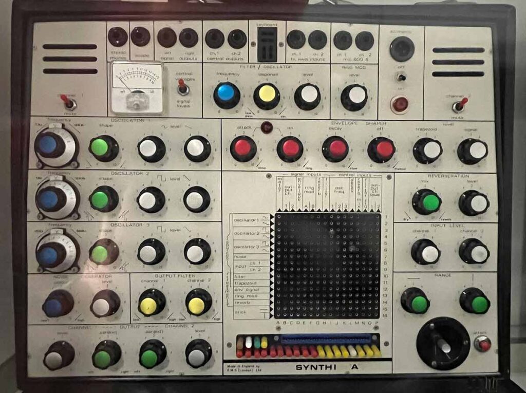
For one of our teachers, who owns a EMS Synthi A (see picture), I created a setup to be able to interface with the CompLex module.
A short quote from Wiki: “The EMS Synthi A and the EMS Synthi AKS are portable modular made in England. The Synthi A model debuted in May 1971 and then Synthi AKS model appeared in March 1972 a with a built-in keyboard and sequencer. The EMS Synthi models are notable for its patch pin matrix and its functions and internal design”.
EMS Synthi A
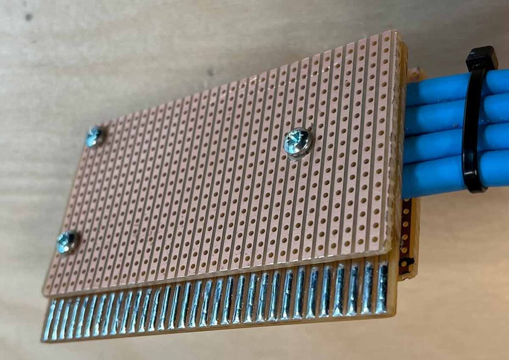
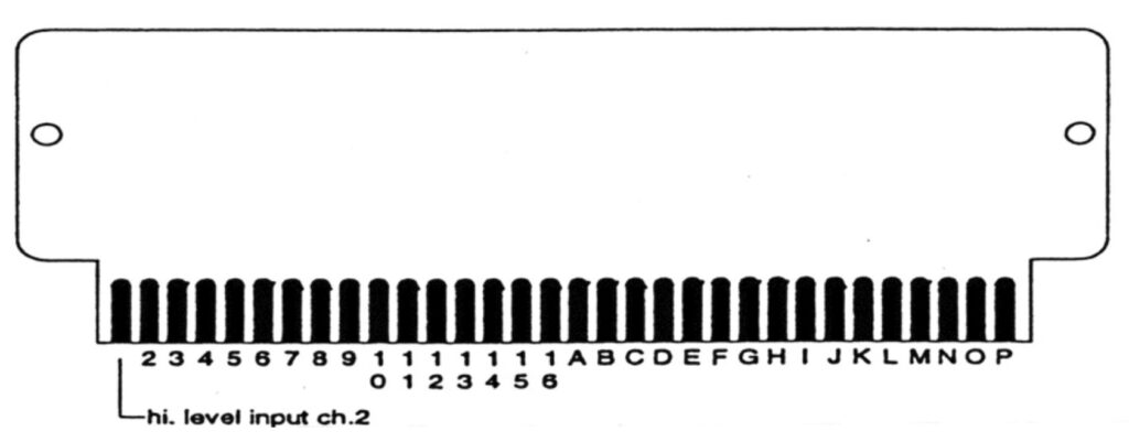
The Synthi A has a pin-matrix but also a 32-pin connector that is directly connected to the 16 ins and outs of the matrix (located directly under the pin-matrix). Instead of connecting the pins to the matrix, I created a first version of a connector that is directly connected to the CompLex matrix. So instead of placing the pins in the matrix we can change the setup with OSC and software!
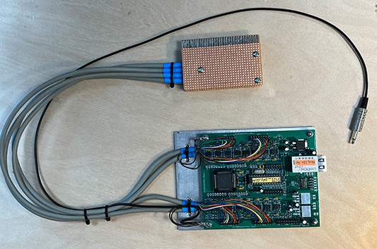
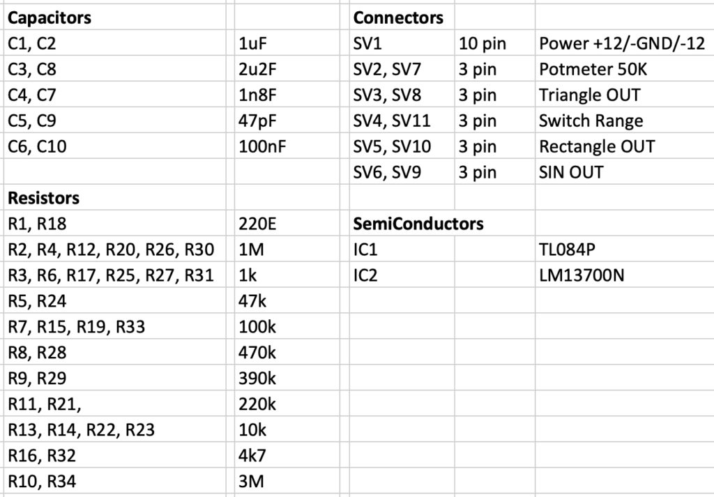
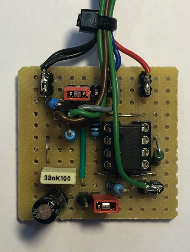
As a follow-up of the small LFO (see last post), I designed a Printed Circuit Board (PCB) of the LFO, so it is easier to make this circuit for anybody who is interested. Since the LM13700 chip has two OTA’s onboard (2 x Operational Transconductance Amplifier) I also created two LFO’s. (like the design made by Ray Wilson).
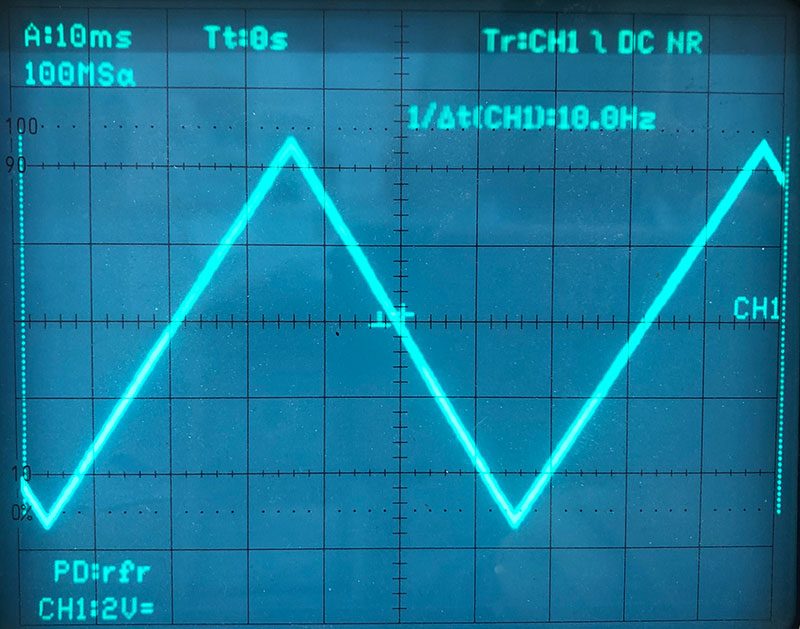
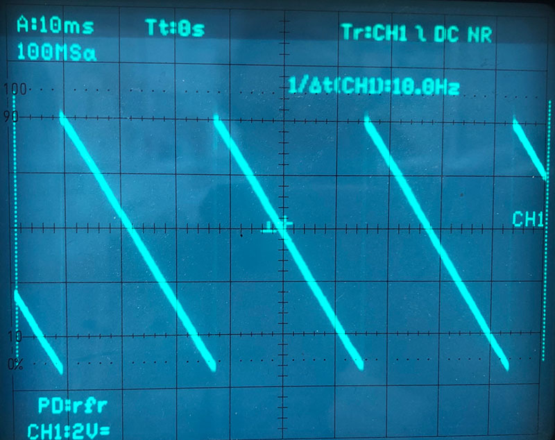
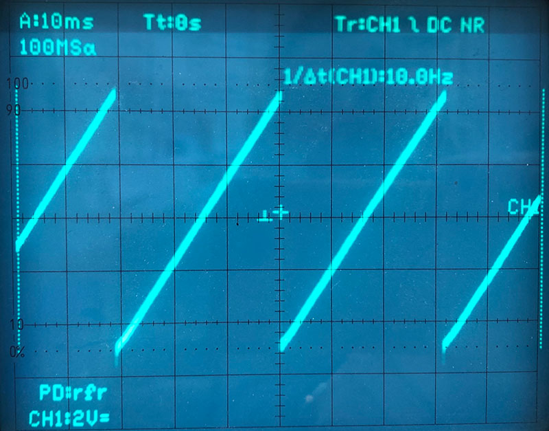
One LFO has 3 outputs: rectangle, triangle and sine-wave. With a potentiometer of 50K the frequency can be changed. The switch is added to be able to change the frequency range.
The circuit takes +12V, GND and -12V. It uses the Eurorack standard power-supply connection. Please consider that this is a very basic LFO circuit and notice the amplitudes of the output signal are not constant over the frequency range. But still, a great LFO!
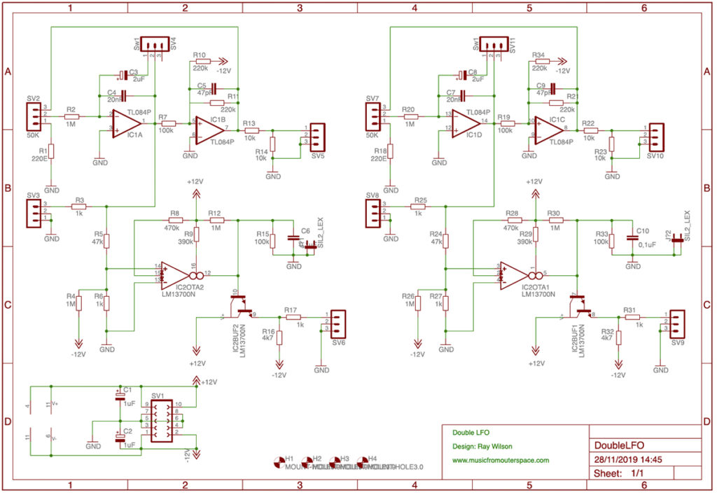
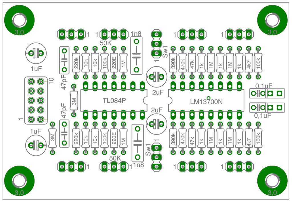
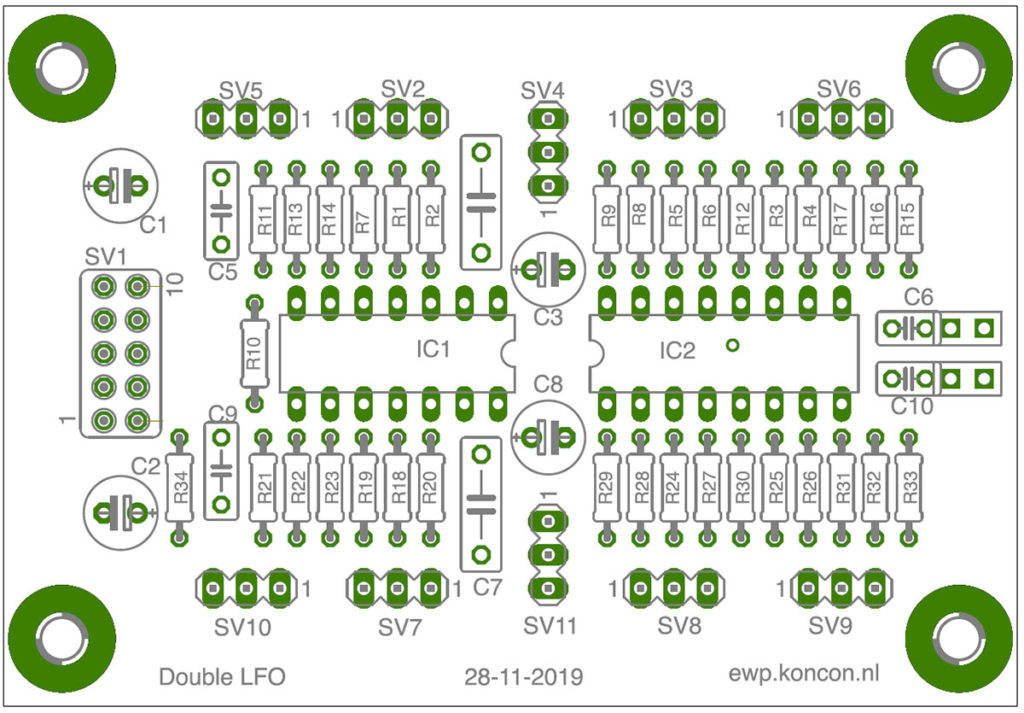
The Eagle circuit drawing. Two identical circuits.Printed Circuit board with resistor valuesThe component side of the board with all component-references
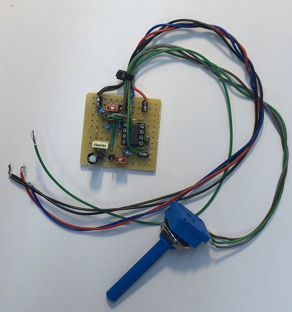
Lately more students ask for an oscillator that is capable of generating real low frequencies, a so called Low Frequent Oscillator (LFO). So I made a simple and small LFO.
LFO with frequency range from 500Hz – once every miniute
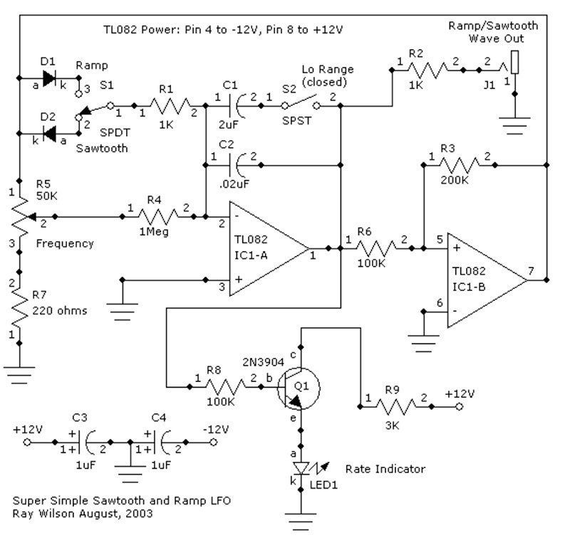
If I have to look for a good design circuit related to synths, I always visit the website ‘musicfromouterspace.com’ with designs from Ray Wilson. Great designs! For an more extended explanation and circuit description, please check this page: The only thing part that I did not implement in my version, is the LED and the extra capacitors making the power supply ‘smooth’.
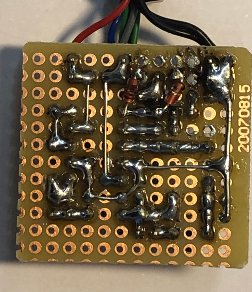
Bottomside (sold side)
Topside (Component side)
I made a real small version, since it had to be placed into a really small housing. Instead of the switches, I used two jumpers, changing the frequency-range and the waveshapes..
When you build a complex device like a Vocoder in combination with 2 x B&K band filters, it is inevitable to document the configuration. “Always be kind for your future self”. In other words, I made new documentation of the Vocoder, which I will share with you and myself.
Vocoder in its final 19″ housing
The two B&K filters and the 19″ rack with electronics in between. The electronics is stacked into one big 19″ cabinet and it actually is quiet full with wires, connectors, printed circuit board, fuses and power supplies. If the electronic setup needs to be adjusted, I need a roadmap of all the connections. I chopped all the different functions in the design into parts and I refer to the letters A,B,C until H.
To refresh the setup of the Vocoder, the following overview:
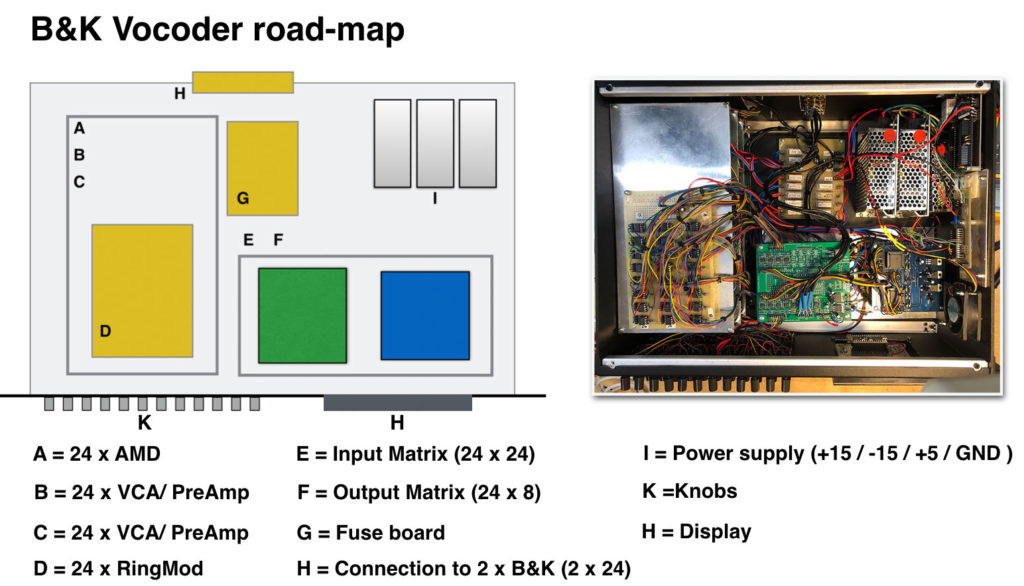
In the explanation of the roadmap I will refer to letters A, B … until H.
On the right side the actual inside of the 19″ housing and on the left side a reference to all the different functions. To make efficient use of the available space, I stacked all the pcb’s in four layers. These are A, B, C and D.
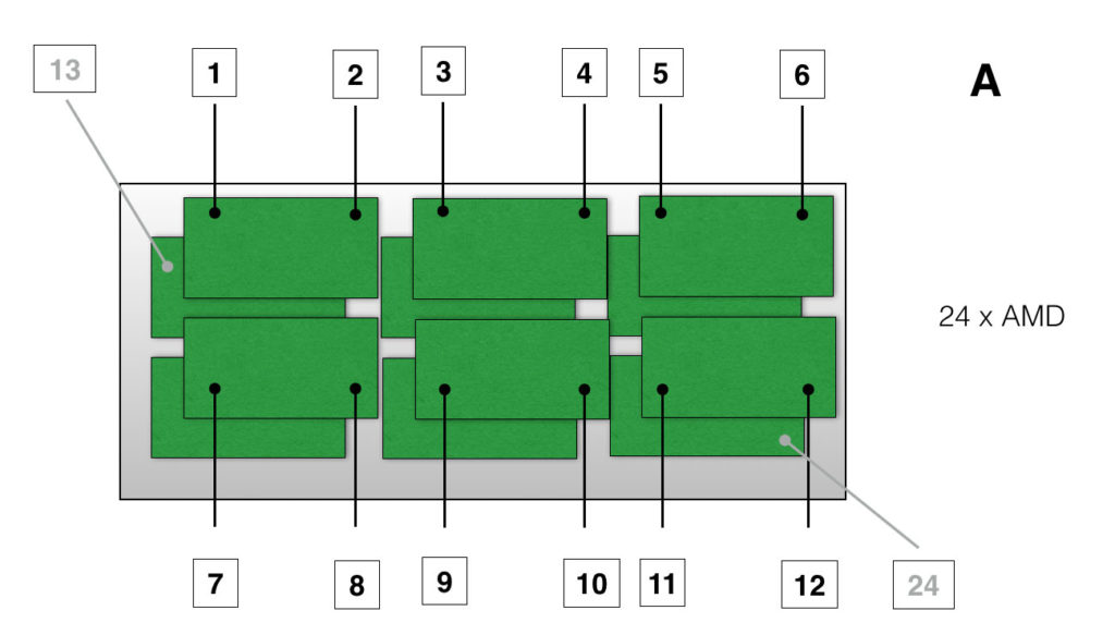
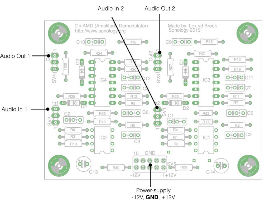
Which input is located where on the PCB. That is for me the most important part of the documentation. In this way I can find my way around when we have to modify or repair the electronics. So the connections of the 24 times AMD. The layout of the pcb itself can be found here
Every AMD printed circuit board has two AMD’s onboard. Since I need 24 Amplitude Demodulators, I had to mount and connect 12 boards in total. The top 6 pcbs cover input 1 -12 and the lower ones 13 -24 (grayed out).
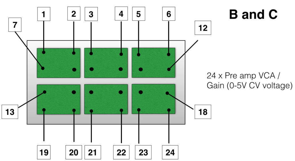
The next two layers consist of 48 x pre-amp, or B and C. The signals coming form the the filters need to be buffered and conditioned (amplified or attenuated). Also the design of the PCB can be found here
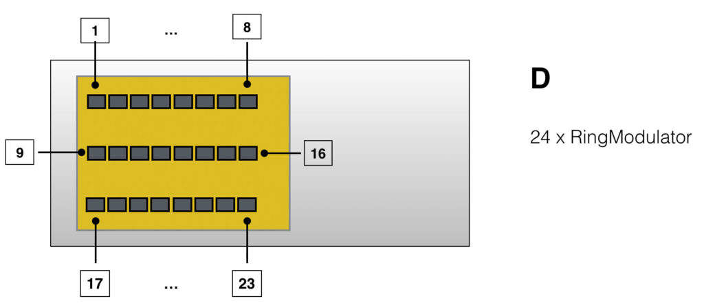
The top layer of the PCB stack, are the 24 times ring-modulator, referred to as D in the layout.
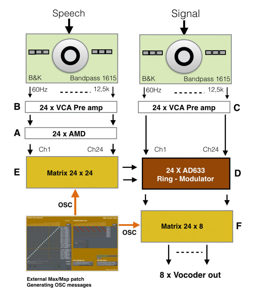
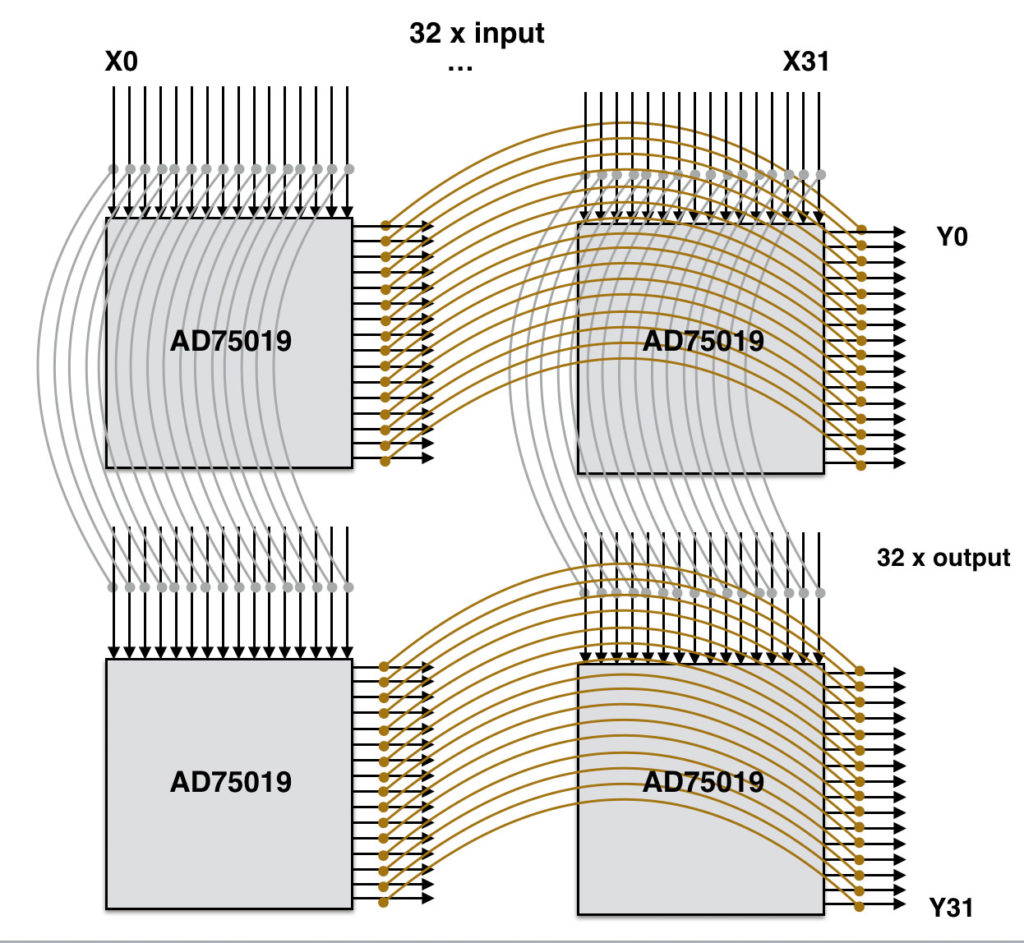
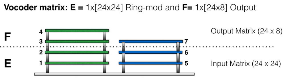
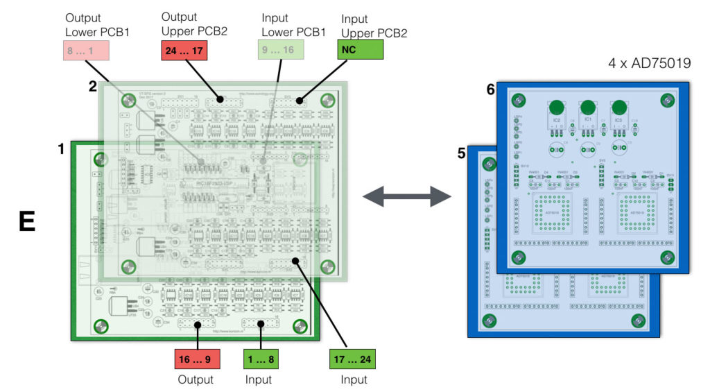
To be able to switch all the in’s and out’s, the Vocoder is designed around two big matrix setups, E and F. Martrix setup E is the matrix of 24 inputs and 24 outputs, that connects the two signals ‘Speech’ and ‘Signal’ together, creating the specific vocoder sounds. Since the matrix chip, the AD75019 only has 16 in’s and 16 out’s (16×16) we have to applpy more chips. To be able to switch 24×24, we need 4 matrices.
A few years ago I already made a design for a PCB where I could mount and route two AD75019 chips. So when I need 4 of the chips to be connected like the figure above, I need two boards. This is shown below(E):
On the left two ‘CompLex’ boards (green) ( 1 and 2) with 16 in and 16 out. I use the these CompLex boards because they already have the right amount of (inverting) opamp implemented, so the summing function as well as the output drive can be used. On the right the 4 matrices (2 x blue) creating a total matrix of 32×32, from which we use only 24×24.
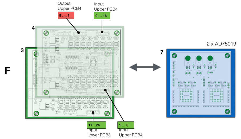
With the output matrix (F) we only need one (blue) board.
‘G’ indicates a fuse-board. This is a board has multiple fuses connected between the different boards (A, B …) and the massive power supply (+15V/2000mA, -15V/2000mA, +5V/7000mA). To avoid ‘fire’ or damage when something on a board goes wrong, the application of a fuse-board is absolutely necessary.
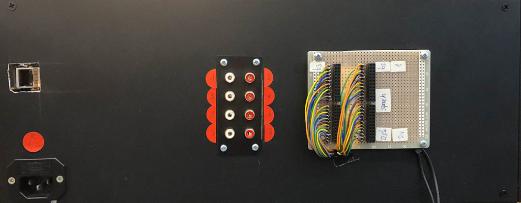
Backside of the vocoder
The backside of the Vocoder has connections for the two B&K outputs, 8 vocoder outputs, the mains power-supply and the connection for the LAN cable.
The display of the Vocoder is still under construction (K)- that is, the programming of the whole thing. My colleague Andrea Vogrig is taking care of this part of the project. The display is a 32×32 RGB led display
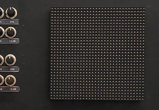
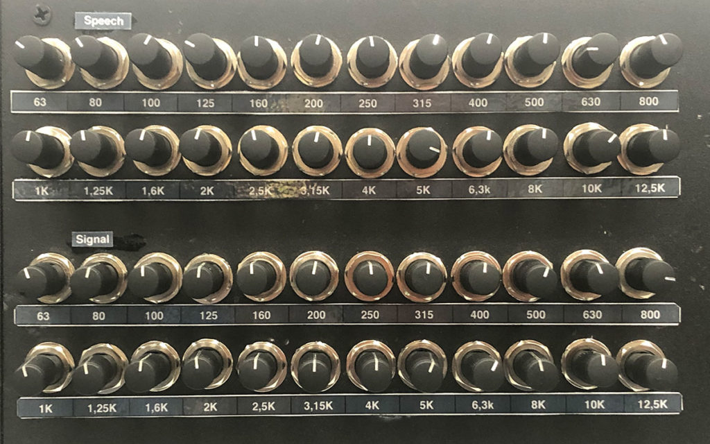
‘K’ is referring to the knobs. There are 48 knobs in total. 24 for the spectrum of the speech input and 24 for the spectrum of the input-signal. The circuit of the VCA is explained here. These 48 potentiometers generate a voltage between 0V-5V, driving the onboard VCA’s. The great idea behind this setup is that in future the 48 VCA’s can be driven by external voltages as well. For now this is not implemented yet.
Frontpanel
Last but not least I share a video clip which gives you an indication of the sound of the Vocoder. I recorded it simply with my iPhone and the speech signal is from the book ‘Junky, by William S. Burroughs’. When the vocoder is completely finished, I will make a better video. For now its a great indication.
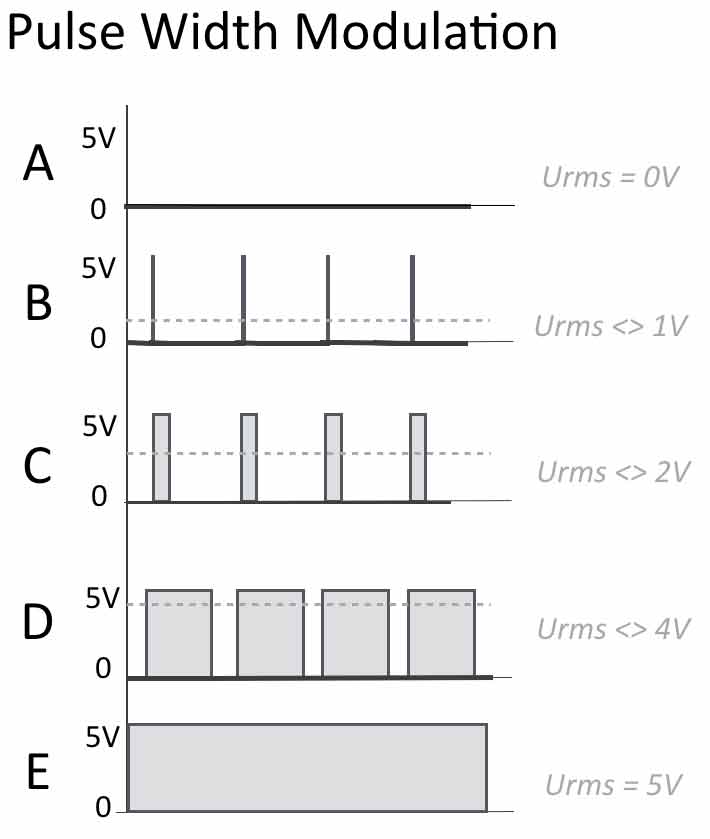
I added some new figures and adjusted some text about how to drive actuators and how to connect sensors. What is Pulse Width Modulation (PWM) and how does this relate to ‘AnalogWrite’ in your code? How can you make a LED light up when the terminal output is zero?
In this new year I work edon a new project, the B&K Vocoder. What is a Vocoder? If you do not know, but you want to know :), please check this link.
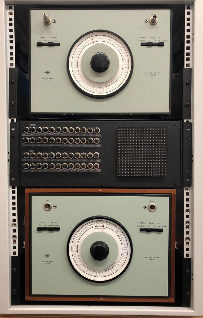
To create this Vocoder will be a big project that consists of two original B&K Band Pass Filter Sets Types 1615 (see photo) in combination with a 32×32 OSC controlled audio matrix – the CompLex. The 3rd octave B&K-filters are made in the 1970’s and make use of real big coils. This makes the sound of these bandpass filters very unique. Since we have a few of these filters and we can use the OSC-controlled audio matrix to change the routing, the whole device will be an interesting composing tool for the department of Sonology. See also the block schematic below.
Two identical Bruel & Kjear Bandpass filter 1615:
A more detailed description of the circuit can be found here.
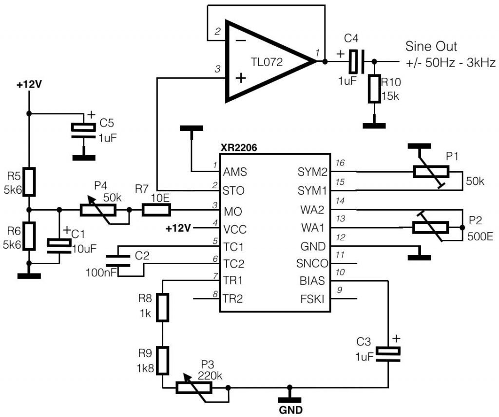
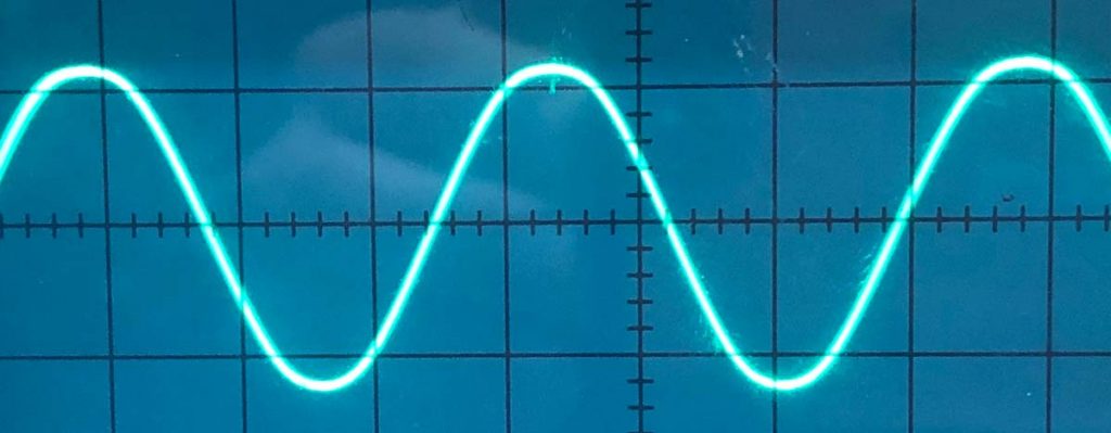
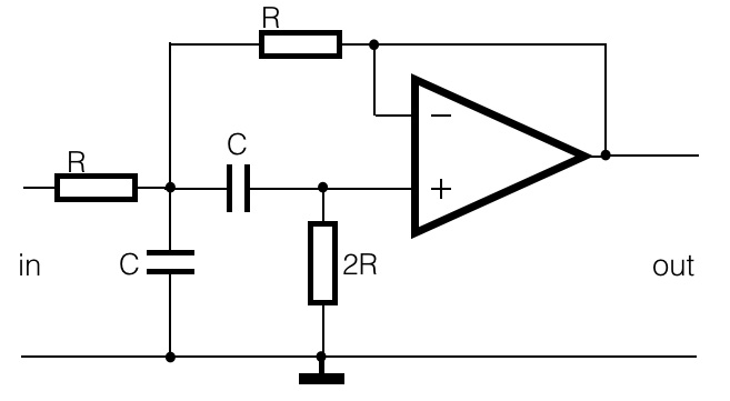
For those of you who want to built a relative simple sine-wave generator, take a look at this circuit (scroll down). For some performances of the Composition department at the Royal Conservatory, we made 6 of these sine-wave generators. They are easy to build and show a relative good quality sine-wave.
This is a photo of the oscilloscope, showing the actual output of the sine-wave generator. Not perfect, but nice!
Some of the recent questions I heard from the students were about filters. The world of filters, whether active or passive, is a complex one. There’s a lot of documentation about this subject and if you have to design a particular filter for a particular frequency, you will encounter quiet complex math. I added some examples of second order LP, HP and Bandpass filters and included some on-line calculators.