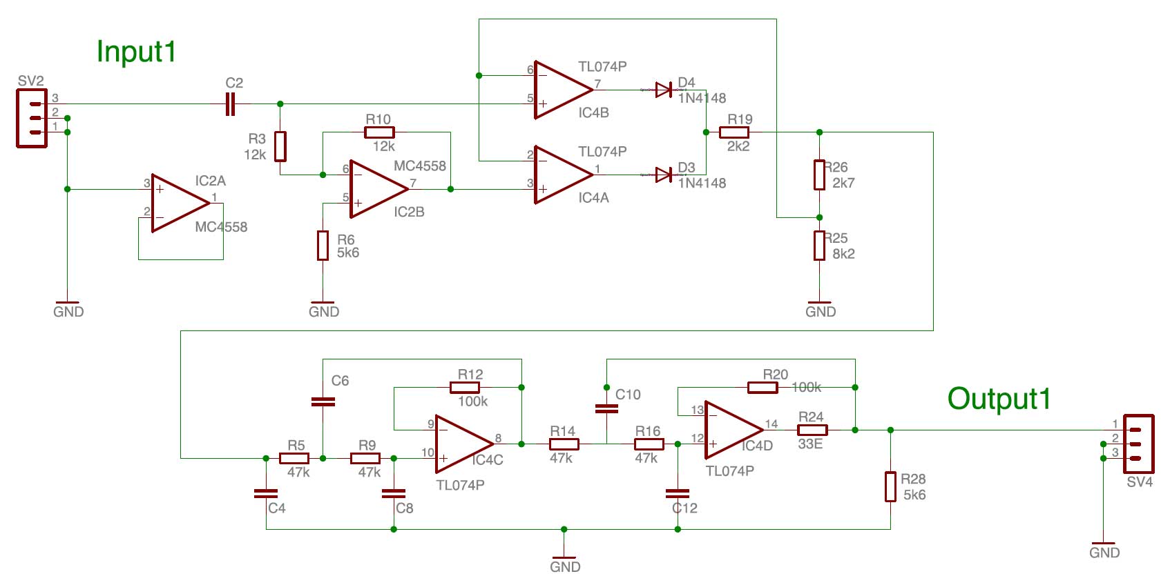
The AMD used in the B&K Vocoder is developed at Sonology in the 1970’s. It is an amplitude follower that uses double sided rectification and also the ‘speed’ of the follower can be adjusted by setting different capacitor values. So for lower frequencies the follower can be set ‘slow ‘(F=10 / 0,7Hz). For mid- and higher frequencies the speed can be set to F=40(2,8Hz) of F=160(11,3Hz).The PCB of the AMD consists of two identical amplitude followers. In the circuit below only one channel is shown.
From input1 the audio-signal (through C2) is inverted with IC2B. IC2A is not in use in this board and is connected to ground. Both the inverted- and original signal are connected to the opamp-pair IC4A en IC4B where the diodes as part of the feed-back loop realise a double sided rectification. IC4C and IC4D are two active low pass filters placed in series (creating a steeper slope). The values of the capacitors determine the cut-off frequency and thus the ‘speed’ variable F (see table).
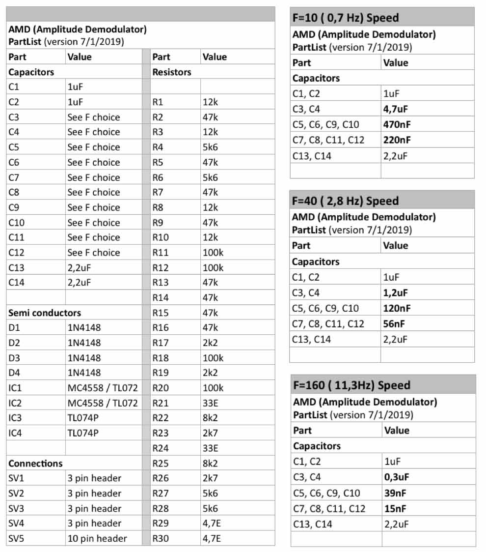
De Partlist shows the parts of the whole PCB (two channels)
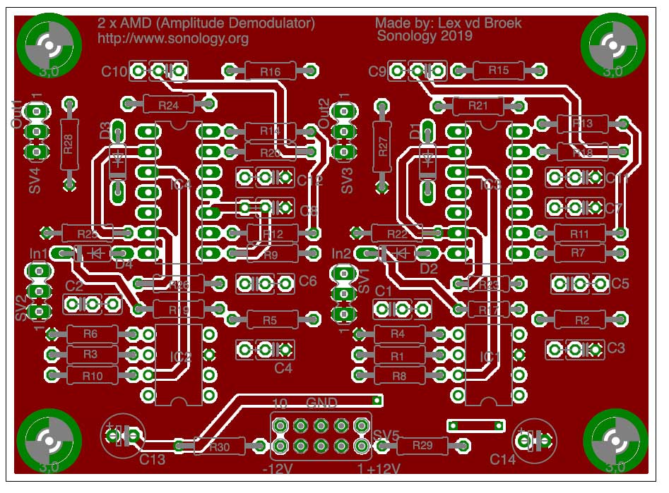
The setup of the (redesigned) AMD Printed Circuit Board:
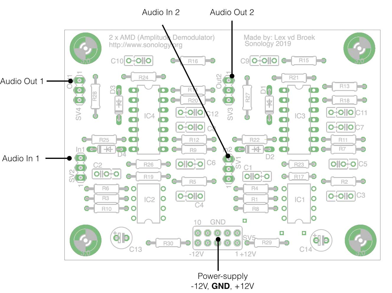
Bottom layer of the Printed Circuit Board
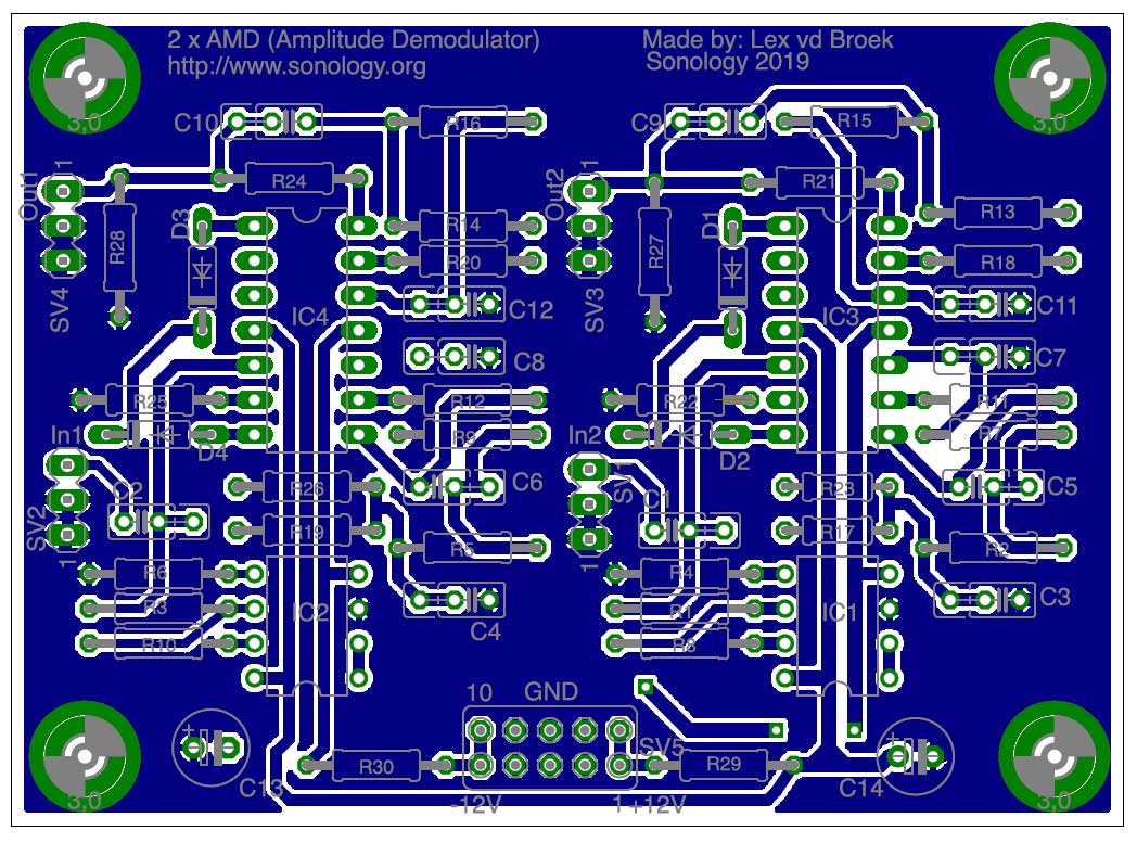
Top layer: