For the Sonology Voltage Controlled Studio, I developed a new design for the Voltage-driven Amplitude Modulators (V-AMM). The previous version of this circuit—still in use in the studio today—was created around fifty years ago and had reached the point where replacement and redesign were necessary.
The new design is based on the V2164 OTA chip for amplitude modulation. I previously used this same chip in the design of the B&K Vocoder. In its standard configuration, the V2164 exhibits an exponential response of approximately –33 mV/dB. This means that when the control voltage is linear, the resulting gain curve is exponential. For the V-AMM system in the studio, however, a linear response was preferred.
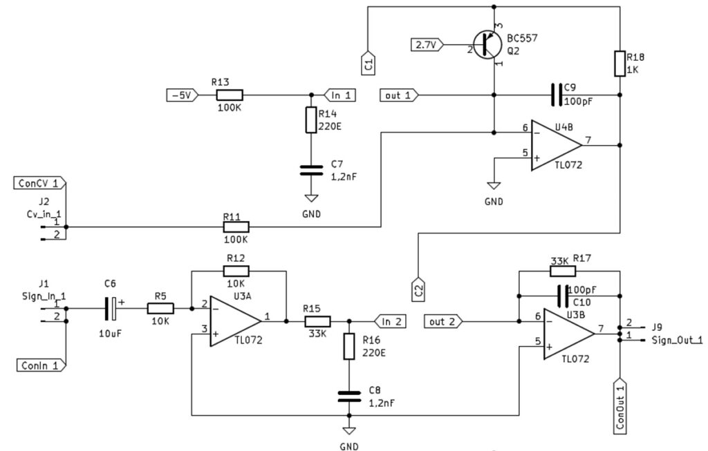
To achieve this, I implemented the compensation method described in the V2164 application notes. A PNP transistor, with a reference (clamp) voltage of –2.7 V applied to its base, is placed in the feedback loop of an op-amp. This circuit generates an exponential control voltage, which compensates for the chip’s inherent exponential gain behaviour. The result is a linear amplification curve.
The disadvantage of this approach is that a single VCA channel requires two channels of the V2164. The new design of one channel:
 |
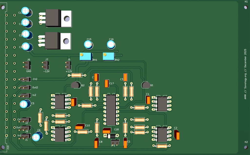 |
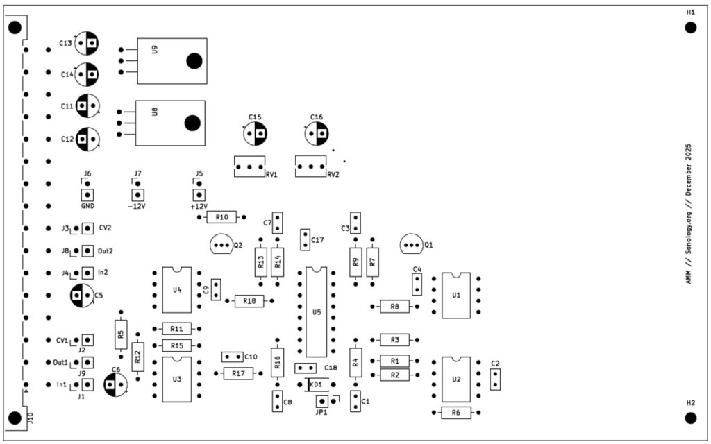
The printed circuit board has been designed to fit the Sonology studio racks, operating from the standard ±30 V power supply and using the DIN 41612 multi-connector for all I/O connections. I also added extra pins so the PCB can be used without this multi-connector, making it suitable for anyone who would like to build and use the board independently.
 |
 |