Introduction
The Remote Controlled Studio is a small modular synth setup of which all functions can be controlled with OpenSoundControl messages (OSC). The OSC-messages are converted into analogue control voltages, switching relays and changing hardware connections with a voltage controlled patch-panel. The onboard (old) Minimac and network-switch make it possible to stream the audio result (like internet radio) throughout the network. An additional USB stereo audio-interface enables the possibility to record and playback audio results. And with the 1/4” jack patch-panels multiple connections can be made with external devices.
The original setup of the RC-studio was a to create a environment for testing the OSC-devices that are developed in the Electronics Workshop. Converting OSC to control voltage or relay switching, this could all be tested in the RC studio. Years ago the eight old VFUG’s (Voltage controlled Function Generators) that used to be part of the analogue studio of Sonology (Bea-5), were replaced by twelve new VFUG’s. Re-using the 8 old VFUG’s was the first step towards the RC studio as it is now.
Since the RC-studio was also a (small) part of my master research and I did a presentation during a colloquium in the beginning of 2017, the project started to draw attention. How does it work and how can you control it? It’s important to say that this project will always be work in progress. In order to get feedback and keep on improving this RC-studio I will place it in a studio (Bea-6) that is available for every student.

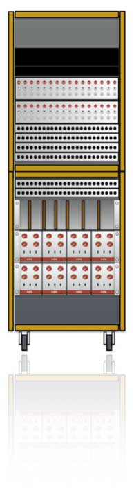
The 19” module with the plastic glass-plate in front holds all the important modules that make the RC studio what it is. The modules are build by hand on ‘Eurocard’ printed circuit boards (PCB’s) that comply with the Sonology Bea-5 standard. The eight old VFUG’s can be found in the middle.
1. This board is a combination of a noise generator and a Voltage Controlled Pulse Width Modulator.
2. The CompLex. This board is the result of my master-research project and holds the voltage controlled matrix that can be used as matrix but also as audio-generator.
3. A voltage controlled state variable filter (VSF)
4. The 12 bit DA board. This board holds 16 times 12-bit Digital to Analogue convertors. It receives OSC data an it will convert this data into DC control-voltage from 0V-5V.
5. The one unit high 19” module on top holds the XPort- This network-port (embedded webserver) receives the OSC-information from the connected host (your computer) or the users of the internet and converts it into RS-232 data that is send to the different modules. The small green LED’s indicate power-ON and message receive.
6. The whole studio does have a lot of different power supplies. This is one of them, providing the RC-studio with -15, GND and +15V.
7. A Vosim (Voice Simulation board). This board generates bursts of half sine waves, triggered by an external trigger.
8. ADSR-module. This module is a combination of a ADSR generator and a VCA combined.
9. The first version of the matrix. This is the heart of the RC-studio. The inter-connections between the different modules will be realizes through this module.
10. and 11. The old VFUG’s (Voltage controlled Function Generators)
12. The output patch-panel with 1/4” jack
13. The input patch-panel with 1/4” jack
Quick start
Since we all want to get started with a new device without reading a manual, try this instructions to get the RC-studio up and running. If you want to know more about the architecture and possible communication syntax, please read this manual. It’s always useful!

How to start, step by step
1. Switch on the RC-studio by connecting the mains (230V~). The connection can be found on the backside. The RC-studio will switch on, you hear a ‘chime’ (from the starting MacMini) and the network switch needs some time to properly boot (around 1 minute)
2. Connect the CAT5 cable to your computer and make sure your computer has a static ip-address in the 10.1.60.xxx range (no automatic ip-assignment).
3. Download the RC-studio Max-patch at: http://www.ipson.nl/maxmsp-patches. The patch is created with Max/Msp version 7.1.0
4. Start the Max/Msp patch and make sure the right ip-address and port number are set in the patch. See [1] in the figure.
5. Connect the output of the Yamaha mixer patch-panel [7] connection 23 and 24 (out L and out R) to the input of a mixer and make sure the speakers are connected as well.
6. First start with a simple test to check if the connections work. Check the right matrix example in figure <$n:figure:qr>.
On the right matrix (CompLex or SPG = Signal Path Generator), select CV5 and CV6 to be the control voltage for VFUG5 and VFUG6 (see [2]). Select the frequency-range of 1k (audible) and select a wave-shape on both VFUG5 and 6 (see [1]) – you will hear the clicking of the relays. Select the output of VFUG5 and VFUG6 to be connected to left/right (see [3]). You should hear a mix of two sine waves. The frequency of the sine waves can be changed by changing the value of CV5 and CV6.
If you hear a combination of two wave shapes and you can change the pitch by changing the control-voltages, the RC-studio is ready to be used. Enjoy!
IF the RC studio doesn’t work … read the manual 🙂
If the RC-studio is not responding to your OSC-messages, check your network- and audio-settings again – switch off your wireless network for example. Maybe you forgot something? The RC studio is a complex device, so it’s easy to loose control. Be sure to also check the content of the manual. There’s a lot of useful information that might solve your problem. If you (after reading this manual) still can not make it to work, please contact me – I will assist you if I’m available.
Max/Msp patch

The Max/Msp patch shown in figure above can drive the whole RC-studio. It generates all the correct OSC-messages for driving the modules and the two matrices. This patch is a personal (partially chaotic) interpretation, and please feel free to re-design the patch or rip it apart.
1. This is the IP number of the RC-studio with the right port information. The Max/Msp patch sends (udpsend) all OSC data to this IP-address and port (10001).
2. VFUG 1 and VFUG 2 with the settings of wave shape, frequency range (10,100,1k,10k) and the pitch. Both VFUG1 and 2 are directly connected to CV1 and CV2 (outputs 1 and 2 of the OSC-CV DA convertor) and can not be patches to external control voltages – in other words, the pitches are fixed to CV1 and CV2.
3. The pitch control voltage can be patched of VFUG3 and VFUG4.
4. Control voltages 3 and 4 are available on input 5 and 6 of the /ma matrix.
5. The matrix object driving OSC-matrix /ma. By clicking on one of the dots of this matrix (making a connection from the input to the output) a OSC-message will be sent from your computer (the Max/Msp patch) to the RC studio. In total there are 256 connections (16 x 16) that all can be set and cleared. Storing a patch can be realized (see 15) with the use of the preset-objects. A <shift> click will store the patch.
6. More Control voltages that are available on the /pa matrix, or CompLex.
7. VFUG 5,6,7 and 8. All four pitches of these generators can be patched through the matrix.
8. This is the same object as use in (5), but it generates a different OSC-message (/pa). Also these patches can be stored in the preset object underneath.
9. Since the CompLex is a generator, there are a few different ways to sequence through presets. When button (9) is pressed, the Max patch will sequence through the active preset-bank that is indicated at (12). This is a so called local sequence. You can change the amount of presets in the sequence (1-32) and the direction (up, down, pendulum). The time in msec (milli seconds) indicates the speed of the sequence.
10. The preset-banks (1-32) can also be uploaded into the local memory of the CompLex. In this way, the sequence through the different presets can be triggered by external voltages. The configuration of the external triggers and control voltages can be set at (13).
11. Pressing this button will upload the active preset into the local memory of the CompLex generator or matrix.
12. This is the indication of the active preset bank.
13. As explained in (10), the configuration of the external voltages and triggers can be set in this area.
14. The ADSR module has 4 faders (variables) that can be changed: Attack, Decay, Sustain and Release. All four variables are being sent into one separate OSC-message.
15. For both the OSC-matrix (/ma) and the CompLex (/pa) the patches can be stored in these preset-banks.
16. Extra control-voltages that are available on the external patch panels (output).
17. Instead of sequencing in order (up/down/pendulum) through the patches in a preset-bank, you can also create a list of different preset numbers. When the button ‘List’ is active, the sequence will play according to this list.
Block schematic
The setup of the RC-studio changed many times the last years and it will keep on changing when more users share their ideas. In the figure below a complete overview is shown of all the internal and external connections. The colors that are used, refer to the colors used within the Max/Msp patch.

The heart of the RC-studio consists of two matrices (the two grey boxes). The first matrix (OSC-matrix, /ma, light grey) is the older matrix module (the first version I made). It is capable of switching 256 switches On/Off at once to create connections or patches.
The second one (CompLex, /ma, darker grey) is the matrix with the nickname ‘CompLex’ and is a result to my master research project. The CompLex is a voltage controlled and voltage triggered audio matrix, capable of switching at high speeds. The ‘/ma’ and ‘/pa’ indication refer to the OSC-string address-tag that has to be used to drive the matrices.
The ‘/ma matrix’ has 16 audio/cv inputs and 16 audio/cv outputs. It has multiple modules connected to it (see figure) like the Vosim, a VSF, Noise, 4xVFUG and a VC-PWM generator. It has 3 dedicated output connections that are directly linked to 3 inputs of the second matrix, the CompLex – these are TRA, TRB and TRC (transfer). The CompLex has 2 direct output connections as well, connected to the input of the OSC-matrix called TR1 and TR2.
The OSC-matrix also has 3 outputs that are directly linked to the 3 voltage control inputs: CV-speed, CV-preset and trigger input. The CompLex, also called the Voltage Controlled Signal Path Generator (VC-SPG) is capable of switching between patch presets at high speeds (audio rates). The OSC-matrix can therefor drive the CompLex matrix. Both the matrices have direct connections with the patch panels making it possible to connect to external devices – your music world!
OSC-Messages
The RC-studio configuration depends on correct OpenSoundControl messages, that comply with the right syntax. Within all the modules that are able to receive OSC-messages, small powerful micro-controllers handle the incoming data. If the received OSC-message is not compliant, the messages will be ignored and there will be no result. The next few chapters explain in detail the syntax of the OSC-messages.
The RC studio is driven by OpenSoundControl or OSC. OSC is a protocol for communication among computers, sound synthesizers and other multimedia devices that are optimized for modern networking technology. Within the design of the RC studio only OSC-messages are used to communicate with the external computer. An OSC-message consists of three parts: an OSC address-tag, an OSC type-tag and the OSC argument(s).

All OSC-communication is achieved with blocks of 4 bytes (1 byte = 8-bits) and the characters use the standard ASCII coding for the definition of the right symbol. In the figure you will notice the extra ‘zero’ after the address tag ‘/pa0’. This zero acts as a separator between the address-tag and the type-tag and it completes the complete data-string to a multiple of 4-bytes. After the definition of the type-tag consisting of nine 16-bit integers (9 x i), two zero’s are added again to complete the multiple of 4 and to accomplish the separation between the type-tag and the OSC-arguments. Both the /pa and the /st strings contain a total of 9 integers [v0 – v8]. For the communication with the RC studio, the address-tag (/ma in the figure) has multiple values:
/ma : this address-tag is used for driving and changing the switches in the OSC-matrix
/pa : abbreviated from the word ‘patch’ this is used to drive and change the switches in the CompLex matrix.
/cf : this short OSC-message, consisting only of one OSC-argument is used to configure and control the CompLex. You can define at which speed and which external voltage it should be triggered.
/v1 : the OSC to control-voltage board uses the v1 address tag to create 16 times 12 bit control voltages.
/rx : This address tag with different numbers (1-8) drive the switches of the VFUG’s 1-8. It changes the wave shape and frequency range
/ev : The onboard ADSR modules can be driven by one short OSC-message starting with ‘ev’.