| Resistors: | |
| R1 | 0 Ohm |
| R2 | 220 Ohm |
| R5 | 27 kOhm |
| R6 | 27 kOhm |
| RN1 | Resistor array; sil9; 100k (BE AWARE of PIN 1! .. black dot) |
| RN2 | Resistor array; sil6; 100k (BE AWARE of PIN 1! .. black dot) |
| RN3 | Resistor array; sil5; 100k (BE AWARE of PIN 1! .. black dot) |
| Semiconductors: | |
| IC1 | IC socket 40 pins PIC18F4420 |
| IC2 | 7805 (mounted on the ALU heatsink underneath the board) |
| IC3 | LF33 (mounted on the ALU heatsink underneath the board) |
| D1 | 1N4001 |
| Capacitors: | ||
| C1, C2 | 33pF | |
| C3 | 470uF / 16V** | Polarity! |
| C4, C7, C8, C9, C14 | 100nF | |
| C5, C6, C10, C11 | 2u2F | Polarity! |
| C13 | 10uF | Polarity! |
| Miscellaneous: | |
| Q1 | Crystal 7,3728 MHz |
| DC1 | Dc adapter pcb mount |
| SV1-SV11 | female headers |
| JP1 | jumper (0E) |
| sw | Reset switch mcdtsa6 |
| LED | red/yellow/green |
Testing the IpSonCompact
When all components are on the right spot (check the directions, the polarity), you can connect the power for the first time. I’ll advise you to do this check without the processor in place. Connect the power with an adapter set to 9V-12V, with the plus in the middle. Take a look at the figure.
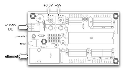
On the left side of the board, the 12-9V DC is connected to the PCB (+ in the middle!). You can measure the values +3.3V and +5V with a multimeter on the upperside of the board. When the values are not as written below, turn off the power and check the connections. If the values are ok, turn off the power and insert the processor (IC1). Be aware of pin 1. Turn on the power again. Your IpSonCompact is ready to go!
Connecting the IpSonCompact to the net
When connecting the IpSonCompact to the net for the first time, there are some configurations to be made before your computer and the IpSonCompact can exchange highspeed data.
The onboard server (xport) can be configured with a normal web browser or with telnet (terminal software). What is there to be configured? The IpSonCompact needs to know which IP-address the remote computer (=the IP-address of your computer) has and which port on that IP-address will be available. As soon as this has been configured, the IpSonCompact can exchange data with the remote computer (is your computer).At the Electronical Workshop of the Royal Conservatory, we already initialized the IpSonCompact, so it has a default IP-address and a default local port. The ip-address of the Ipsoncompact is written on the PCB (Printed Circuit Board). The local port will be 10001.
There are two ways to connect the IpSonLab to your computer:
– direct connection with the IpSonCompact and your computer (both cross- and normal ethernetcable can be used)
– connection through a switch or hub.
Configure the IpSonCompact with a webbrowser:
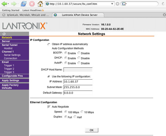
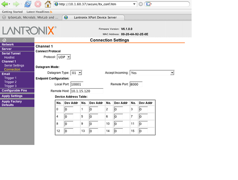
Start Firefox (other browsers do give some problems) and fill in the ip-address of the IpSonLab (Xport). If the login window pops up, just hit enter. You can protect your xport by setting a password. Default the name and password are empty. The loading of the pages will take a short while, so be patient. It will load a Java applet. Select channel1 / Connections and fill in your IP-address at remote host and remote-port. When the changes are made, make sure you save the new settings, by clicking “ok” underneath. Then hit apply in the menu and the device will reboot. Take closer look at the screendumps below.
In the given example, the Ip address of the IpSonCompact is 10.1.60.37
Screendumps:
– network settings (setting IP address IpSonCompact)
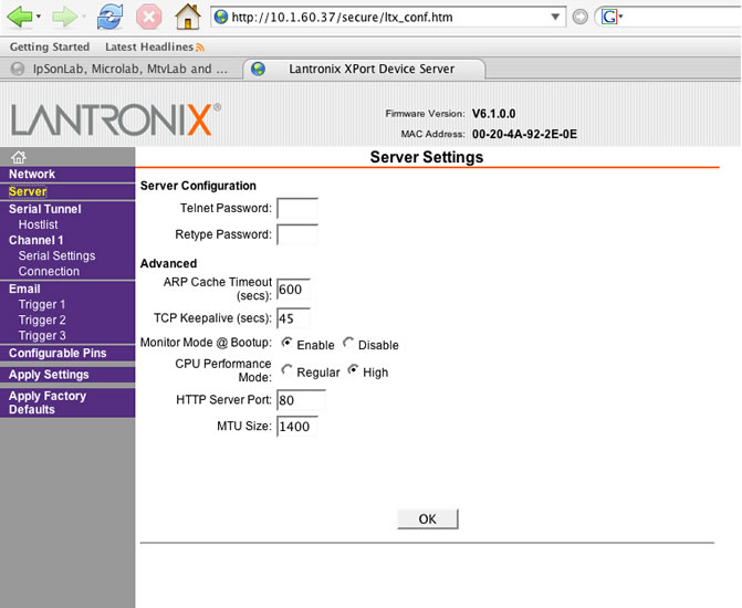
– Server settings (setting the High speed option)
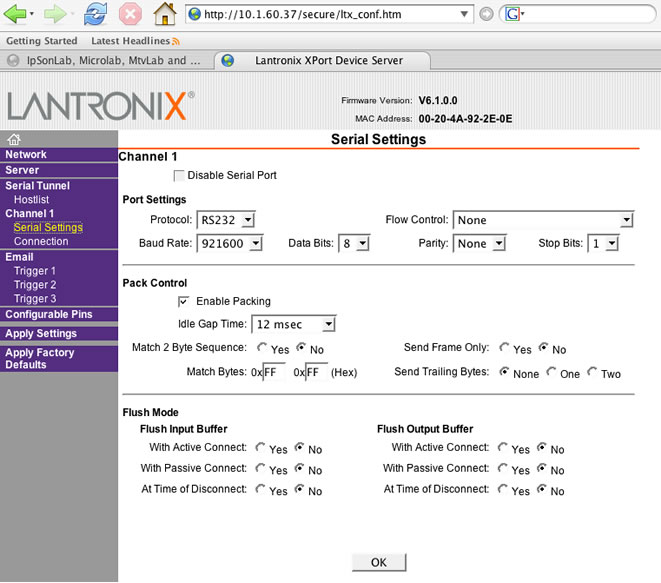
– serial settings (setting internal communication of the IpSonCompact)
– connection settings (remote host settings)
Configure the IpSonCompact with telnet: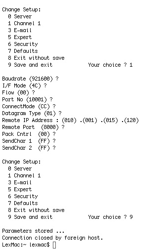
(port 9999 only!)
Make sure the IpSonCompact is connected and the power is on. Open the terminal on your computer (both Mac and PC) and type telnet at the prompt:
telnet <enter> Then open the connection with the IpSonLab (example ip-address 10.1.60.1):
Open 10.1.60.1 9999 <enter>
The number 9999 is the telnet port number. Within five seconds you have to hit enter again. At this time you are connected with the IpSonCompact and you are able to configure all kind of settings. Be aware that the general settings are already made and the only thing that has to be changed is the remote IP-address and the remote port number** (default on 10001).
Check the figure on the right.
Select an option on the menu by entering the number of the option in the Your
choice ? field and pressing Enter.
To enter a value for a parameter, type the value and press Enter, or to confirm a
current value, just press Enter.
When you are finished, save the new configurations (option 9). The unit reboots.
** You can choose your own port number (number between 1000-10000). Be aware of the fact that some numbers are already in use (for example port number 80 for http, port number 23 for telnet)
When you are sure the values are right, press 9 to save the new settings and exit or press 8 if you are not sure you filled it in the right way. Your IpSonCompact is ready to go!
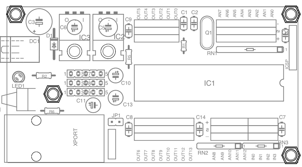
IpSonCompact connections
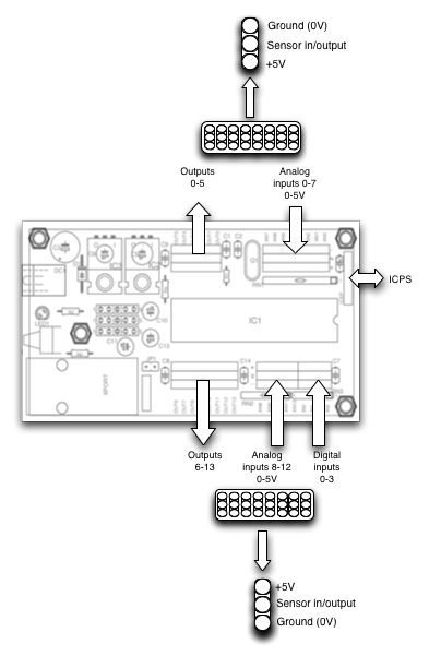 In the figure on the right you can checkout the location of the inputs and outputs. As shown in the figure, the IpSonCompact has 13 analog- (0-12) and 4 digital inputs and 14 outputs. The ICSP input is used to program the processor while it is ‘in-circuit’ This is not a feature for the user; only for the developer.
All inputs and outputs do have the same configuration:
3 connections consisting of +5V, sensor in (or out) and ground (0V).
In case of connecting active sensors, the polarity should be checked carefully.
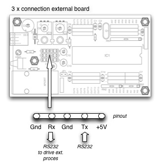
To drive external processes (e.a. 64 relays, 16 12 bit da convertors, 8 x dc engines, steppermotors, servo’s) these connections can be used. Unlike the IpSonLab, the IpSonCompact doesn’t have a second processor onboard, but makes it possible to connect as much processors you want, all connected to the same Xport.
Now your IpSonCompact is connected to your computer and able to exchange data, you can start with Max/Msp (or any other software that can exchange Open Sound Control packages, ea SuperCollider). Within Max/Msp you can read the data from, and send data to the IpSonlab with the ‘udp-read’ and udp-write objects for PC and ‘otudp read’ and ‘otudp write’ objects for Macintosh.For further information about these objects I refer to this website: http://www.cnmat.berkeley.edu/OpenSoundControl/MaxImportant: Within the ‘osc-route’ object at the receiving part, you have to fill in the /ic route for sensor info. All packages sent by the IpSonCompact do have, so called, header information (address tags). You can download an example Max/Msp patch here. As explained in the software versions, the data communication between IpSonLab and Max/Msp, consists of quiet a lot of data. We are bussy to reduce and finetune these settings, so more speed can be achieved and the resolution will be high (10-12 bit).
Max/Msp is receiving:
The IpsonCompact sends out a lot of OSC-messages, or data. To be able to read the right sensor value, the OSC strings have to be ‘unpacked’. You can do this as shown below with the ‘unstuff’ example.
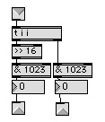
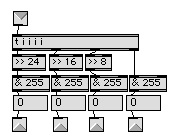
An example of the “unstuff” patch. In this case the unstuffing is actually bit-shifting (place the bits in the right position). Incoming data (osc integer) is been triggered four times (t i i i i). The outputs are bitshifted. The outlets generate four independent 8 bit numbers. For sending 10bits data, the 32 bit OSC string is devided into two times 16 bit. Incoming data is been triggerd twice (t i i). The MSB is shifted 16 positions to the right. Anding (&) with 1023 generates a nice 10 bits number.
 MaxMsp is sending:
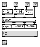
When data is send from Max/Msp to the IpsonCompact, the same process takes place, only inverted. An example of the stuff_4_1 patch: For sending OSC data to the IpSonCompact (the configuration string for example) the data also has to be ‘stuffed or packed. For sending 8 bits information, this has to be done like the sample patch on the left.
Incoming values are first shifted into the right position and then put together (bondo) into the expression that’s logical AND’s the for numbers into on 32 bit integer.
Testing the IpsonCompact.
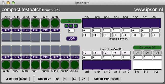
The patch shown below can be downloaded from this website. With this patch you can test all the different features of the Ipsoncompact. It will also run as stand alone application; so if you do not have Max/Msp installed, you still can test your Ipsoncompact.
The button UDPOSC in the middle switches between an older and newer version of the compact firmware. In the old version (OSC mode) the firmware is configured to work with the ‘opensound control object’ that was needed in the older versions of Max/Msp (Version 4 and older). From Max/Msp version 5, the opensoundcontrol object was not needed anymore and the OSC string buildup as changed.
On the right side the 13 sensor inputs can be monitored and the threshold values per input can be set. On the left side the outpuyts can be activated. The button DIG/PWM switches between the PMS and Digital mode. The small fader underneath is only activated in the PWM mode. In the right corner below, the distance measurement can be switched On/Off. In the middle the timer can be activated. The three small buttons below the “timer off” set different values for the timer.