Building the OSC-CV board
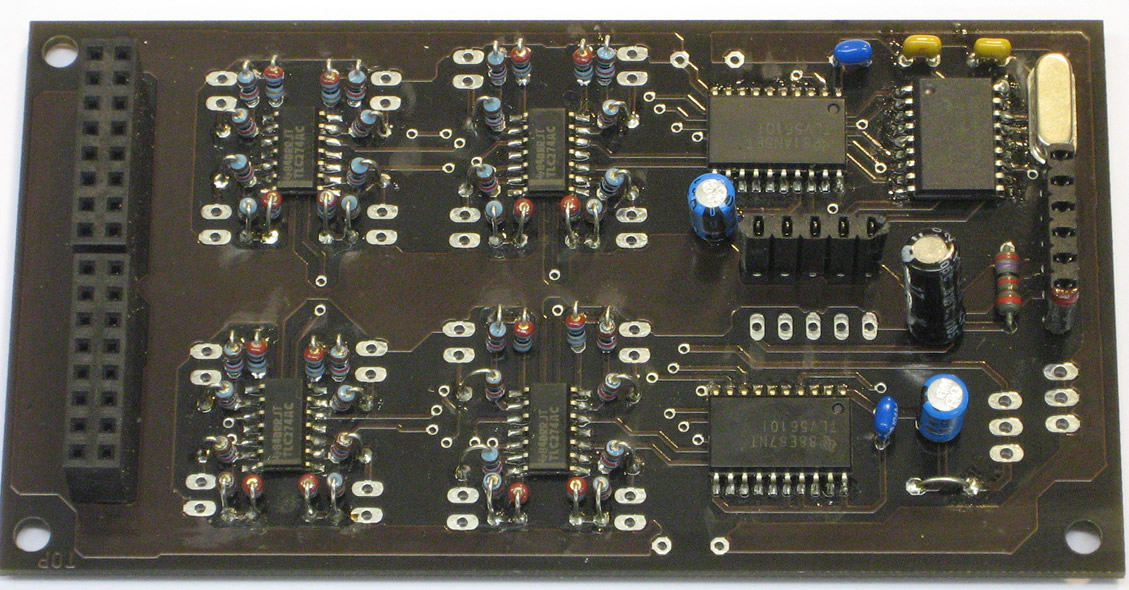
All of the IC’s on this board are SMD (Surface Mount Devices). This means they are really small and quiet difficult to solder to the board. At the Workshop we do have nice and small soldering tools, so it’s not a problem for us to produce the board. For this moment we will start with making this board available only pre-made.
| Resistors: | |
| R1 | 27k |
| R4, R5, R7, R8, R10, R11, R13, R14, R16, R17, R19, R20, R22, R23, R25, R26, R28, R29, R31, R32, R34, R35, R37, R38, R40, R41, R43, R44, R46, R47, R49, R50 |
10k |
| R6, R9, R12, R15, R18, R21, R24, R27, R30, R33, R36, R39, R42, R45, R48, R51 | 22E |
| Semiconductors: | |
| IC1 | PIC18F1220 |
| IC2, IC3, IC4, IC5 | TLC274D |
| IC6, IC7 | TLV5610 |
| Capacitors: | |
| C1, C2 | 27pF / 33pF |
| C3, C4 | 100nF |
| C5, C6, C7 | 10uF (polarity!) |
| Miscellaneous: | ||
| Q1 | Crystal 7,3728 MHz | |
| JP3 t/m JP18 | SIL 2 | jumper for setting x2 amplification |
| SV1 | SIL 6 | ICSP |
| SV2, SV3 | FE08-2 | Output female header 2×8 |
| SV4, SV6 | Sil5 | PowerSupply + RS232 |
| SV5, SV7 | SIL3 | Gnd and Vext |
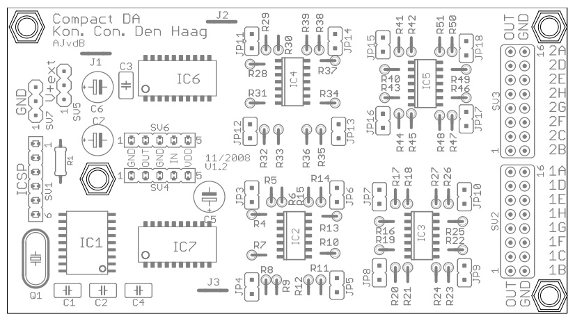
The board will be programmed by us, using In Circuit Serial Programming. This means that by connecting the programmer (used to program the onboard PIC18F1220 processor) to the connector on the left, the right program can be uploaded to the board. This will be done only in the beginning and in case of updates (or special whishes from the user).
On the right side of the board, the outputs are available. In total 16 outputs divided into two sections: 1A-1H and 2A-2H. The order of the connections can be seen in the figure below. When jumper J1 is connected (upper left side), the opamps will be fed by the +5V of the IpSonCompact. This actually means that the control voltage output will never reach exactly +5V, because of the loss of the opamp. When you want to use the full range (0-5V), the best option is to connect the external voltage on the top left side of the board. By feeding the opamps with (for example) +9V, the full output of +5V can be reached. Be aware! — Do not connect the external voltage when the jumper J1 is still conncected— this will result in a damaged processor and/or damaged DA convertors. Better is to always use the Vext and leave J1 not connected (test reasons only).
When the application/board needs to drive a control voltage of 0-10V, a jumper can be set per output to create a times two (x2) amplification (JP3 – JP18). The external voltage should be at least 12V!
The two connectors in the middle (left) do have the same pin layout as the IpSonCompact; this means that the OSC-CV board can be stacked on top of the IpSonCompact. The GND and the +5V for the processor and the convertors are connected here. The Xport output (RS232 datastream from your computer to the OSC-CV board) is directly connected to the Rx input of the PIC18F1220 processor.
Driving the DA_board (OSC String Setup)
Driving the OSC-CV board can be realised with a simple OSC string of 8 (32 bit) integers.
The address tag will be /v1, followed by 8 integers. See the table.
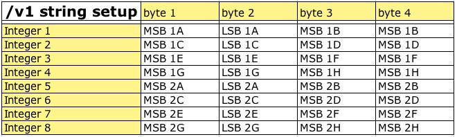
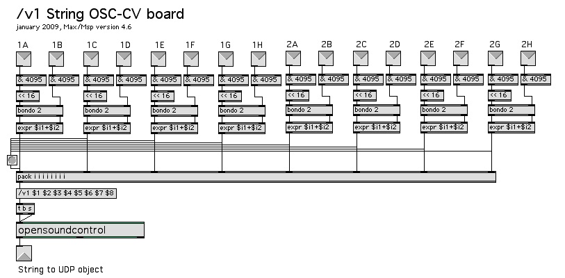
MSB means: Most Significant Byte and LSB therefore Least Significant Byte. The OSC-CV board has 16 outputs with a resolution of 12 bits. For saving time (and thus more speed), two inputs are combined within one OSC integer, as shown in the table. For Max/Msp, Super Collider or other software, it should not be a problem to combine two 12-bit numbers into one 32 bit integer. An example Max/Msp setup can be seen below.
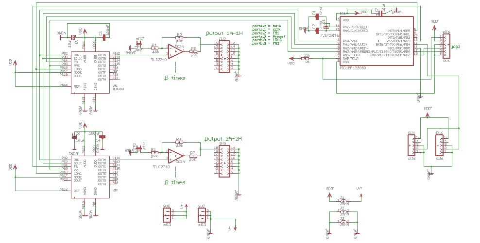
OSC-CV board schematics
The schematics of the board are quiet straight forward. The main proces (handling the incoming data (/v1 string)) from the Xport, will be carried out by the PIC18F1220 processor. The processor and the onboard software will drive the two octal 12 bit DA convertors (TLV5610). The output of these DA convertors are buffered with the TLC274D opamps.
The +5V (Vcc) powersupply for the convertors and the processor, are connected to the IpSonCompact or IpSonLab, both having a 7805 volrage regulator onboard. The external voltage connection (Vext) will only feed the power of the opamps; making it possible to drive more than 0-5V to the outputs. The schematic can be downloaded as a pdf file. The schematic and both the board are designed with Eagle.