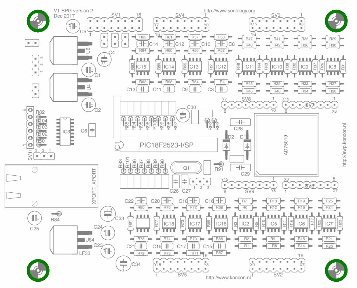
This overview is a guide to build a matrix yourself. First of all an overview of all the components. The layout of the Printed Circuit board of the matrix (the CompLex) is shown below. This layout shows version 2 of the CompLex.
| Resistors | Value | |
| R1-R49 | 10k / 1% | |
| R50, R82, R102, R103, R104 | 470E | |
| R51, R53, R55, R57, R59, R61, R65, R76, R69, R71, R73, R75, R77, R79 |
22E | |
| R52, R54, R56, R58, R60, R62, R64, R66, R68, R70, R72, R74, R76, R78, R80 |
10k / 1% | |
| R86, R87, R88, R89, R90, R91, R92, R93, R101 | 10k / 1% ** |
** These resistors are placed only if needed for specific configuration.
| Capacitors | Value | |
| C1, C5, C24, C25 | 2u2F | |
| C2, C4, C23, C30 | 10uF | |
| C3 | 33pF | |
| C33, C34 | 1uF * | |
| C28, C29 | 100nF | |
| C6 – C22, C26, C27 | 33pF |
* Optional
| Part | Value | |
| IC1 | PIC 18F2523 | |
| IC2, IC5- IC19 | NE5532D, TL072 | |
| IC3 | 74HC595D | |
| D1 | 1N4001 | |
| D2 | 1N4001 | |
| U$1 (Matrix chip + socket) | AD75019 | |
| U$2 (Xport) | Xport |
|
| U$4 | LF33 | |
| U4** | 7812 | |
| U6** | 7912 |
** If configured for Eurorack (connected directly to a power-supply of +12/-12 / +5), these voltage regulators are not neeeded.
| Misc comp | Value | |
| Q1 | Xtal 7,37MHz | |
| SV1 -SV5 | 16 pin header | |
| SV6 – SV9 | 8 pin header | |
| U$5 | 6 pin header | |
| U$3 | 2pin male Header | |
| JP0 – JP25 | Male header |
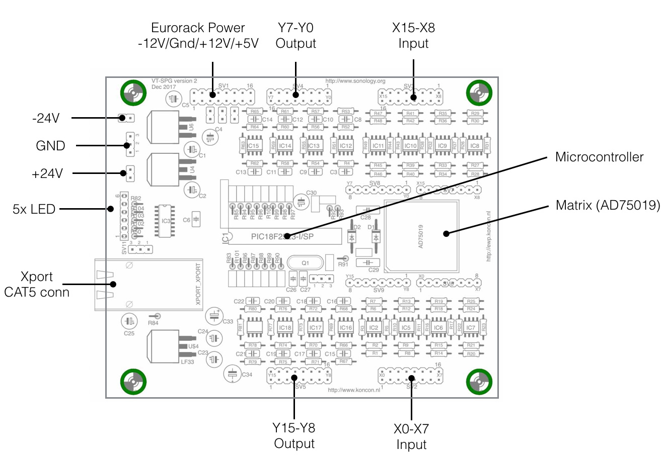
Overview of all the connections on the PCB.
Below an overview of the connections of the PIC18F2523 processor connections on the pcb. The Control voltages and the switches are connected to specific pins. The switches labelled with an * are in fact optional. Almost all switch functions can also be realised within the OSC-string – so driving the CompLex from within the Max/Msp patch.
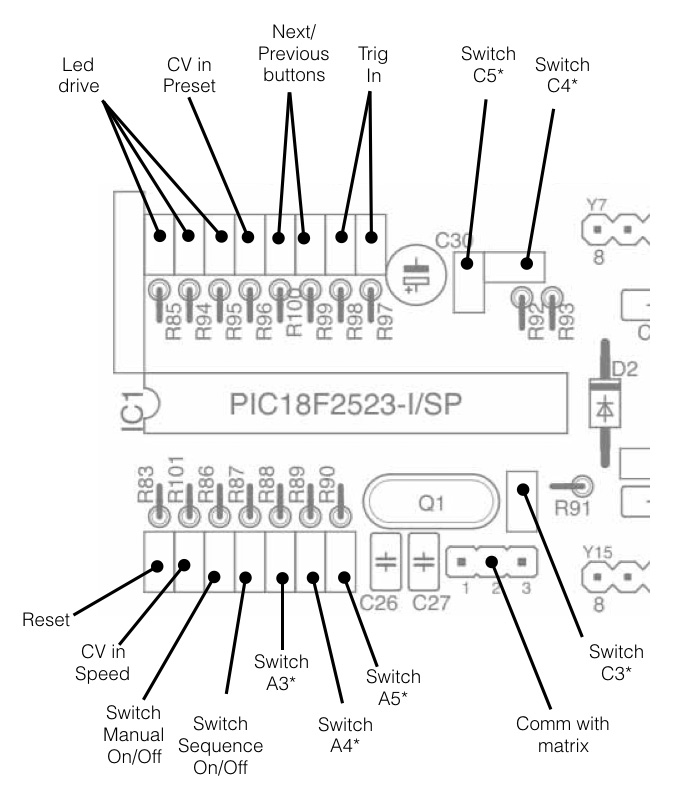
Switch A3* = Switching On/Off the OSC-feedback from the processor back to the computer. When this option is switched on every time the matrix changes, the present status is sent back to the processor. When this option is used, the speed-performance of the matrix will be influenced.
Switch A4* = This switch determines the direction of the local sequence, Up/Down.
Switch A5*= Switching the source of the internal timer. A value can be send with OSC as source, but the value can also be dependend of the CV input (speed).
Switch C3* = This switch can be used to choose between internal or external trigger (sync). Internal sync means the chip listens to the OSC-commands. External sync, or trigger, means the matrix will step to the next preset when it receives a external trigger (positive or negative edge).
Switch C4* = If the matrix switches on the external trigger (C3), it is possible to select the positive edge or negative edge.
Switch C5* = The matrix can can also switch on both edges (see switch C4*) when selecting this switch On/Off. In this way the length of presets can vary when the trigger source is for example Pulse Width Modulation.
As said before, the switches mentioned above are optional. It really depends on how you want top apply the matrix in your practical setup whether you need switches or not.
If you want to knwo more about the OSC-communication between the computer and the mtraix (CompLex), check this page.