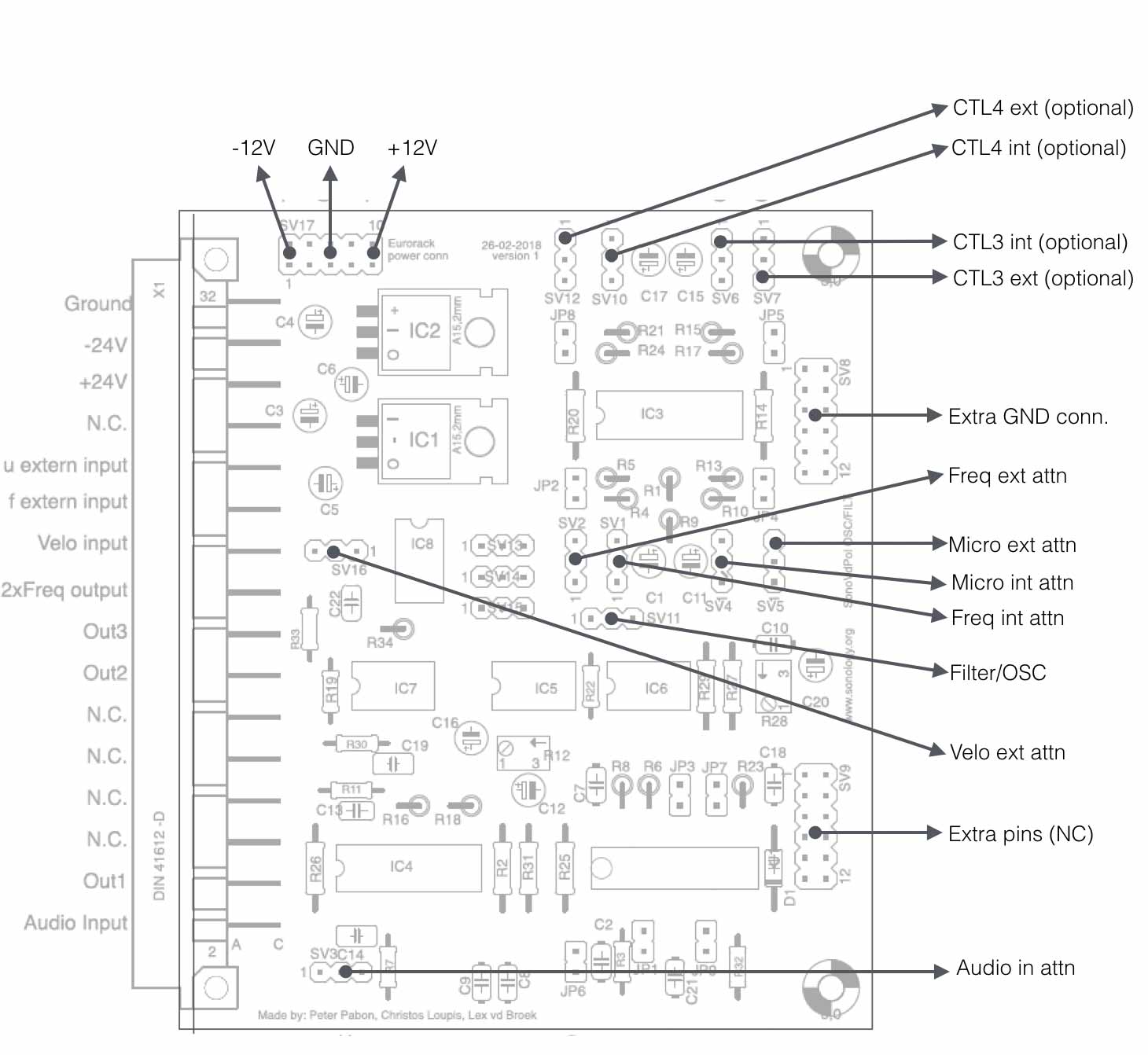
The vdPol Oscillator and Filter is a specific rich sounding analogue device that generates surprising signals – especially when you connect more of them together in a chain. In the setup shown below, the circuit has 4 outputs, and 4 inputs. Since the filter is constructed around a series of integrators connected in a feedback loop (in combination with 4- quadrant multpliers) there are 4 locations within that loop that create different wave-shapes – output 1,2,3 and 4
To change the frequency or the Mu (weight) there are two control voltage inputs. It has 2 audio inputs.
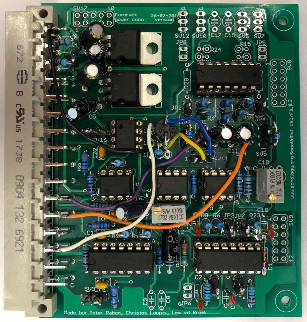
The vdPol filter (see also the blog post) printed circuit board (pcb)
Components
(all components indicated with * are optional)
| Resistors | ||
| R1, R9, R14*, R20 | 47k | |
| R2, R6, R7, R11, R22, R33 | 33k | |
| R3, R8, R23, R32 | 560E | |
| R4, R5, R10, R13, R15*, R17*, R21*, R24* |
22k | |
| R26, R30, | 100k | |
| R16, R18, R27, R29, R31, R34 | 10k | |
| R19 | 15k | |
| R25 | 68E | |
| R12, R28 | 100k trimpot |
| Capacitors: | ||
| C1, C5, C6, C11, C12, C15*, C16, C17*, C20 |
2uF | |
| C2, C7, C18, C21, | 680pF | |
| C3, C4 | 10uF | |
| C8, C9, C10 | 10nF | |
| C13, C22 | 33pF | |
| C14, C19 | 100nF** |
** These capacitors are part of the integrators. This value determines its (frequency) behaviour.
| Semiconductors: | ||
| D1 | BAT19 | |
| IC1 * | 7812 (voltage regulator) | |
| IC2 * | 7912 (voltage regulator) | |
| IC3 | TL074P (socket) | |
| IC4 | TL074P (socket) | |
| IC5 | AD633 (socket) | |
| IC6 | AD633 (socket) | |
| IC7 | MC4558 / TL072 (socket) | |
| IC8 | MC4558 / TL072 (socket) | |
| U1 | V2164D (socket) |
* The voltage-regulars are optional and can be left out when you make the circuit ‘eurorack-compatible’.
| Misc. | |||
| JP1, JP2, JP3, JP4, JP7, JP9 | 0E jumper | Routing of CV | |
| JP6* (not connected in normal mode) | 0E jumper | Mode conn V2164 | |
| JP5*, JP8* | 0E jumper | ||
| SV1, SV2, SV3, SV4, SV5, SV11, SV16 | 3-pin male header | Conn. pins for ext pot | |
| SV6*, SV7*, SV10*, SV12* | 3-pin male header | ||
| Sv13*, SV14*, SV15* | 3-pin | ||
| SV8*, SV9* | 12-pin header | ||
| SV17 | 10-pin header | Eurorack power conn | |
| X1 | 32-pin MAC32L | For analogue studio rack only |