Sensors
(actuators, check below)
Switches
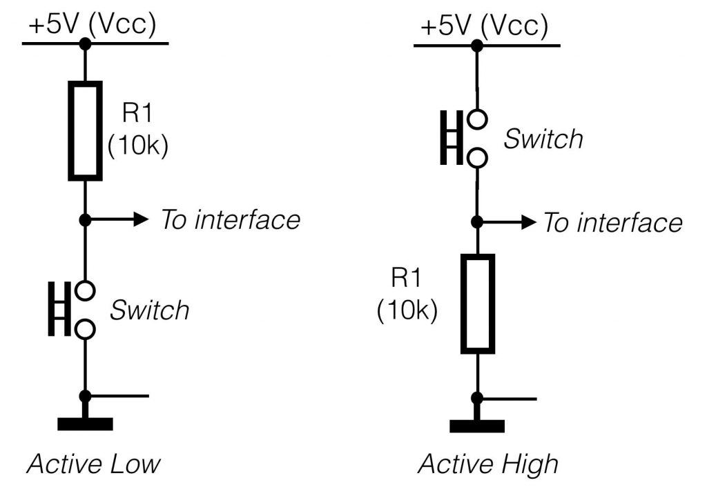
Switches provide a digital input and can be hooked up in the configurations shown on the right. The active low configuration (the switch makes a connection to the ground if it is pushed – the figure on the left), is the preferred method for connecting switches. If you are using a normally open (N.O.) push-button switch, when the switch is pressed, it will send a low level (0V) to the terminal (thus the term “active low”).
Potentiometers
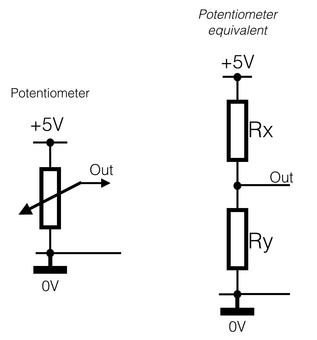
A potentiometer (or “pot”) can be used to provide an analogue input to a interface terminal. Using the configuration below, a pot will vary the input voltage to the terminal from 0-5v – in other words, the full input range of the terminal. 10k is a typical value for use in this configuration, but anything from 1k to 1M should work fine.
On the right side of the figure below the equivalent circuit of a potentiometer is shown. In fact the potentiometer is the same as a voltage-divider circuit Rx and Ry, where the value of the both resistors depend of the position of the pot.
Resistive sensors
Resistive sensors, such as photo-resistors, force sensing resistors (FSR’s) or flex sensors, can be wired in either configuration shown below. Using the left configuration (active low), the terminal voltage
will decrease with decreasing resistance. Using the right configuration, the terminal voltage will decrease with increasing sensor resistance. Use whichever configuration is most convenient for your application.
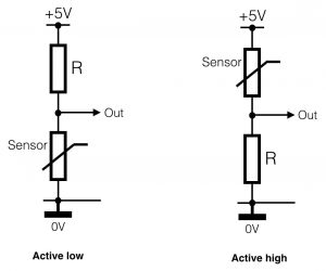
You will also need to select an appropriate value for the fixed resistor R based on the resistance range of your sensor. In general, it is best to select a value for R that gives the largest voltage range for the sensor. The optimal value is R = sqrt(Rmin * Rmax); that is, the square root of the sensor’s minimum resistance times the sensor’s maximum resistance. Once you compute the optimal value, select a standard resistance value that is closest to it. This will give the maximum voltage range for your sensor and thus the best resolution. Use the input min. and max. adjustments for the terminal to compensate for voltage offsets, as described above in the section Analogue input mode details.
Actuators
Digital output: LED’s
 LED’s can be driven by terminals in either digital or analog output modes. Digital output provides on/off, whereas analogue output provides a signal that looks like dimming the intensity of the light – we call this PWM, or Pulse Width Modulation.
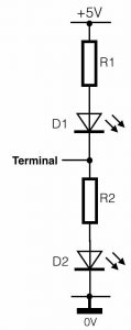
For digital output connected like the figure on the right, D1 will light up when the terminal is 0V (Low) and D2 will light up when the terminal output is high (+5V).
If you want to change the intensity of the light, or the speed of a motor we use Pulse Width Modulation. An Arduino or any other interface is a digital device. And a digital device only knows two states: On/Off, Yes/No, One/Zero. So if analogue output is mentioned, this is not really true. PWM is a method of changing the width of the pulse, so the average signal value will increase or decrease. In the Arduino language an ‘AnalogWrite(variable, xxx); creates a pulse width modulation signal.
Take a look at the picture.
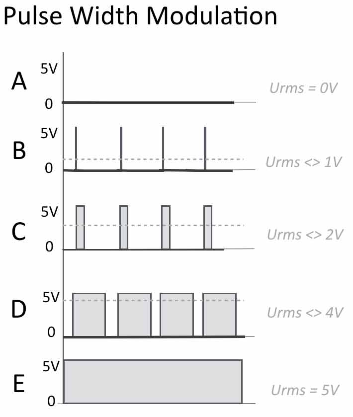
Suppose we have a 8-bit PWM resolution – this means that within the Arduino code (C) you can send numbers from 0-255 (equals 8 bits = 256) to a certain pin.
A: number 0 is sent to the output pin. NO output – value is zero.
B: Let’s say we sent the value 20 to the output (AnalogWrite(pin, 20);). A small pulse will be the result. The average (RMS) value of this signal (over time) will be more than zero. So we have a small increase of the ‘analogue’ value.
C: Now we increase the value to 80. The width of the pulse will increase, sow ill the average value over time. Note that the frequency stays the same!
D: Again an increase, now we are at +/- 200. The time the output is high, is now longer than the time the output is low – so the RMS value is again higher.
E: If you sent 255, the output will be high (+5V), constantly.
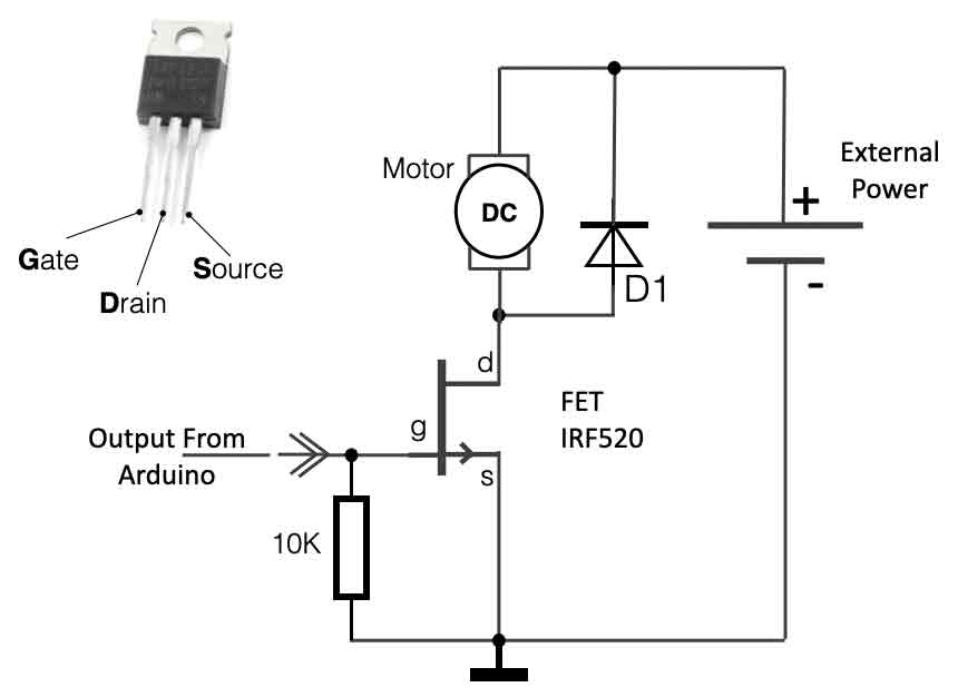
Digital output: Relays, solenoids and motors
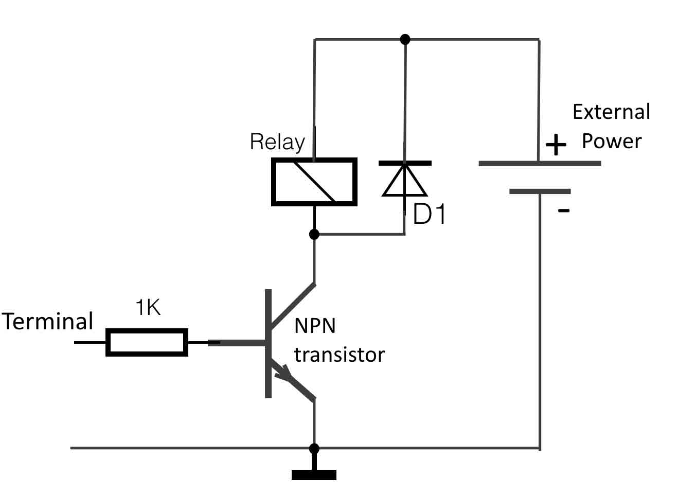
Digital outputs can be used to switch DC electromechanical devices such as relays, solenoids and motors using the circuit on the right. The device is represented as a coil in the circuit. When the terminal outputs a high level (5v), it will switch on the NPN transistor, which will allow current to flow through the coil of the relay and turn on the device.
The diode is required because devices with coils will kick back current when they switch off/On. A diode wired in this way will protect the transistor and power supply from damage. A 1N4001 will work well for many applications. It is best to wire the diode as close to the device’s terminals as possible. Be aware to wire the diode in the right direction (it has a + and a -).